PDP-11 DL-11 Repair (UART)
I quickly ran into a separate problem: the UART wasn’t transmitting data reliably. That pointed me toward a likely issue with the UART card itself.

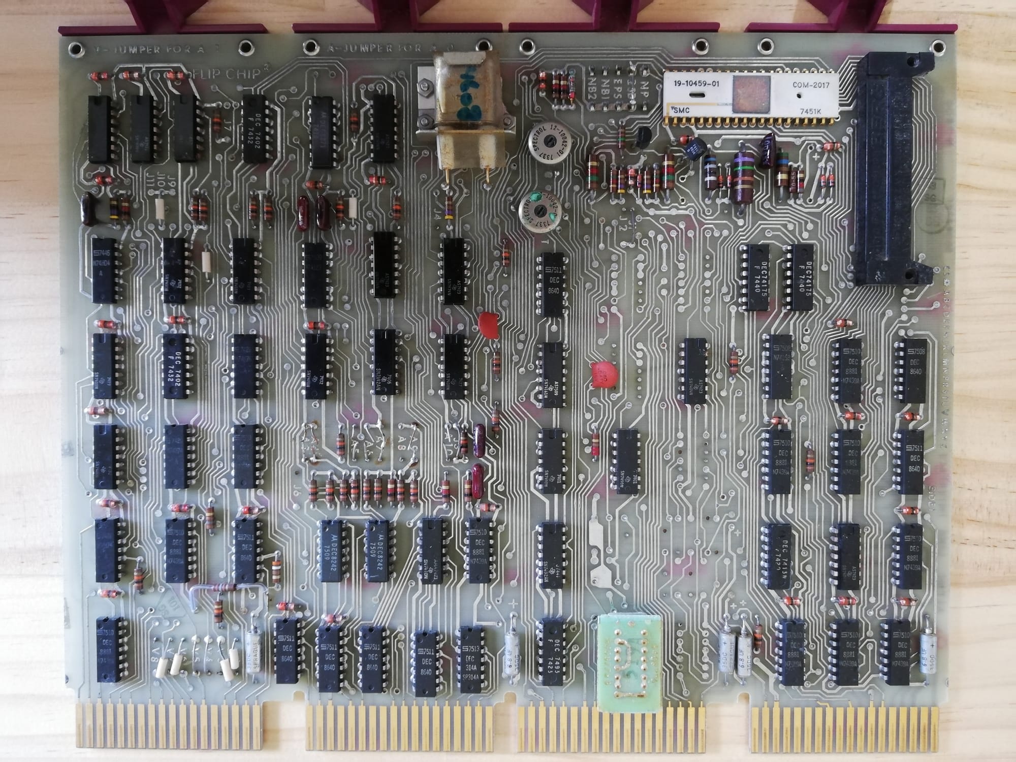
I was diagnosing an issue with my PDP-11/40, where it appeared to be having trouble writing data to I/O devices. To investigate, I used the system’s DL-11 UART to debug I/O space writes. But I quickly ran into a separate problem: the UART wasn’t transmitting data reliably. That pointed me toward a likely issue with the UART card itself.
Symptoms
I had written a tiny little program that would, in a loop, forever, send the character "A" over the UART to my laptop. The program itself ran perfectly. Here it is:
.ASECT
.=2000

wait:
    tstb    @#177564
    bpl     wait
    movb    #101, @#177566
    br      wait
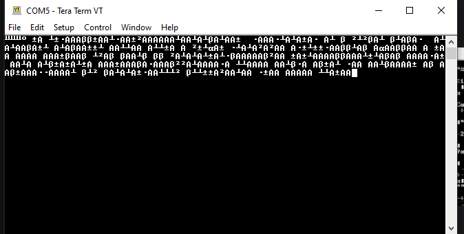
Corrupt Output
Watching the terminal, I could see that some of the "A"s were making it to the laptop while others were corrupt or did not make it at all. Changing software and UART settings did not improve the output.
Initial Theory
I had used this UART before, so I was quite surprised to find that it did not work. My initial thought was that there were ground issues, perhaps one of the wires in the serial cable had broken. I have experienced ground issues in the past with UART.
Initial Investigation
I started my investigation by verifying that the ground wires from the UART were intact and had continuity between both ends of the cable. They did.
Next was to check it with an oscilloscope, doing so immediately revealed a problem.
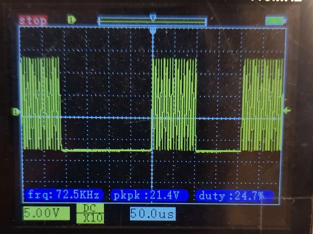
The above image is of the UART TX line. You can see that it has approximately correct RS232 signal levels. The LOW looks good, but the HIGH looks wrong. Specifically, it should not be jumping up and down; it should remain high. This explains why the USB UART was having issues receiving characters. It was unable to correctly sample the UART line.
My initial thoughts were it was having difficulty generating the +V used for the UART. Some UART drives use a "charge-pump" circuit to generate the needed positive and negative voltages. I suspected that circuit, if present, might be having issues.
Checking the RS232 Driver
Looking at the DL11 schematics, I was not able to identify any charge-pump circuit. As it turns out, the DL11 uses the 1488 driver (a part still made to this day), and it was being powered directly from the backplane. Checking the voltages, I found no issue.
Comparing the output to the input of the driver, I was able to conclude that the drive was working correctly, as the input and output matched. I move my investigation to the flop-flop that feeds the driver chip.
Checking The Serial Out Flip-Flop
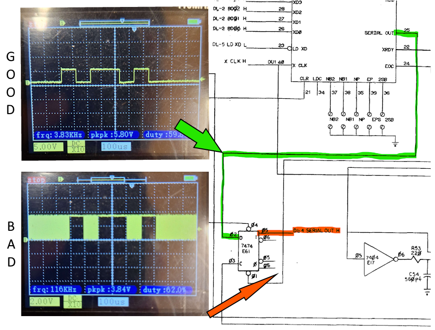
Checking the input and the output of the 7474 flip-flop, it was immediately obvious that something was not right. The clock signal (153kHz) was "leaking" into the putout of the flip-flop, pulling the line high on every clock pulse. The other inputs to the flip-flop were steady at +5V and were not of any consequence.
The Fix
In this case, the fix was trivial; I removed the suspected bad 7474 and replaced it. The UART is now back to working perfectly once more.
Miscellaneous Thoughts
It's interesting, this card has not been used for 30 years. I initially tested it using the unibone, and it worked fine. I then put it away for 3 months, and when I went to use it again, it had failed. It makes me wonder, will I forever be fighting against the degradation of silicon chips? Do I need to stress test new replacement chips?