PDP-11 Floating Point Instruction Repair - Part 1
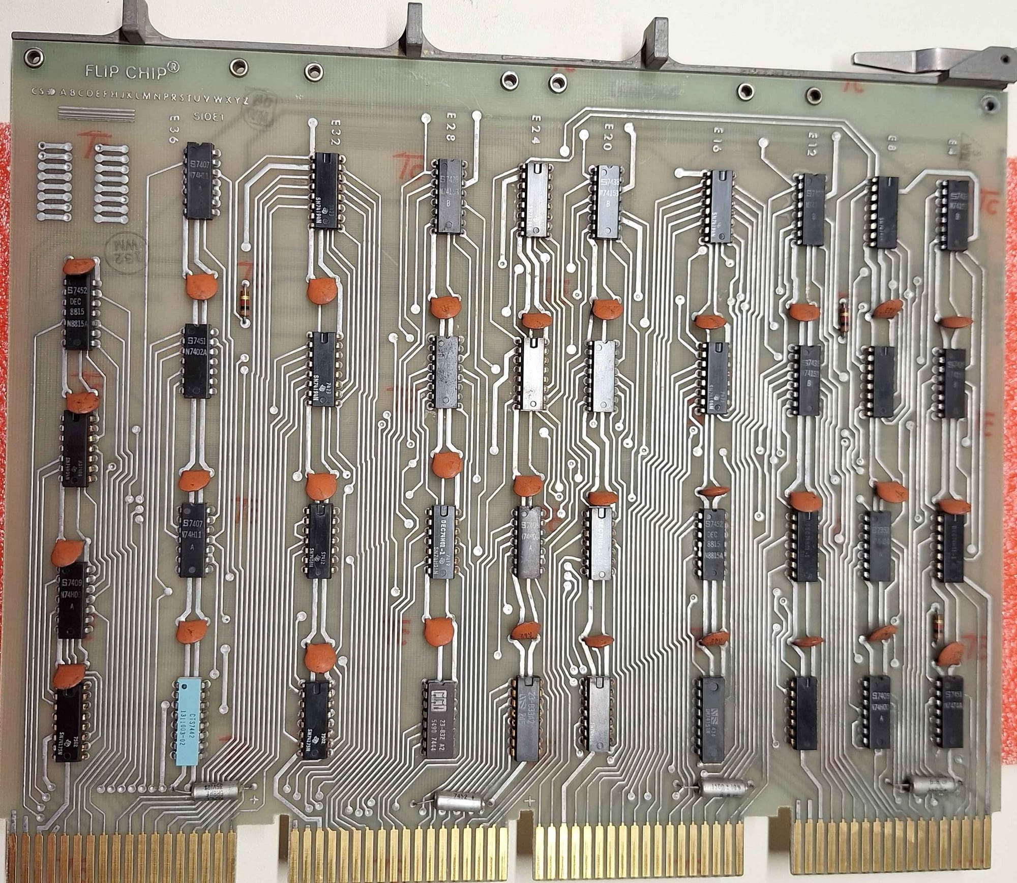
Next up for repair is the PDP-11/40's Floating Instruction Set (FIS) board, also known as the KE11-F. The PDP 11/40 was unique in that the FIS and EIS (Extended Instruction Set) were optional.
The FIS builds upon the functionality of the EIS, adding floating-point addition, subtraction, multiplication and division. This makes the FIS board rather simple in comparison to the EIS board.
Symptoms
- The BQEA diagnostic fails to start and gets stuck trying to check for the KE11-F.
- FADD gets stuck in an endless loop
Debugging
I started by writing a basic program to add 0.00 + 0.00, and spent some time running it at full speed and single-stepping the microcode.
.ASECT
.=4000

DATA:
    .WORD 000000,000000
    .WORD 000000,000000

.=2000

START:
    MOV #DATA, R0       ; Load absolute address 2000 into R0
    CLR (R0)+
    CLR (R0)+
    CLR (R0)+
    CLR (R0)+
    MOV #DATA, R0       ; Load absolute address 2000 into R0
LOOP:
    FADD+ R0
    RESET                   ; Slows the computer down
    BR LOOP
While single-stepping, I observed that the microcode flow was correct for at least the basic example of 0.00 + 0.00. However, when running it at full speed, it would more often than not get stuck in a loop; it appeared to be endlessly trying to shift the mantissa.
Having likely ruled out a microbranch fault, I decided the next step was to study the FIS. In the PDP-11/40 the FIS is implemented as an extension to the base microcode. To do this, the KE11-F has its own set of microcode ROM that is used to extend the width of the system's microword.
I decided to approach understanding the FIS hardware by emulating it in software. I took a similar approach when I first started working on the PDP-11, but unlike then, I decided to emulate only the microcode routine rather than the hardware. I spent the next three days implementing the microcode routine in JavaScript. It has proven to be only a little bit successful; I don't yet fully understand how the PDP-11 does floating-point math. But in the end, I was able to emulate the data fetching and data preparation that is used at the start of every floating operation.
Data Fetch
Armed with my FIS emulation and an example microcode flow from the manual, I sat down in front of the computer and began to compare states between all three.
After going over the microcode for a few cycles, comparing my emulation to the real system was able to pinpoint the fault. During the fetch of arguments for the floating-point operation, the wrong address was being used to fetch data. For example, the correct address was 000070, but the KE11-F was trying to read from 075070; some bits were stuck!
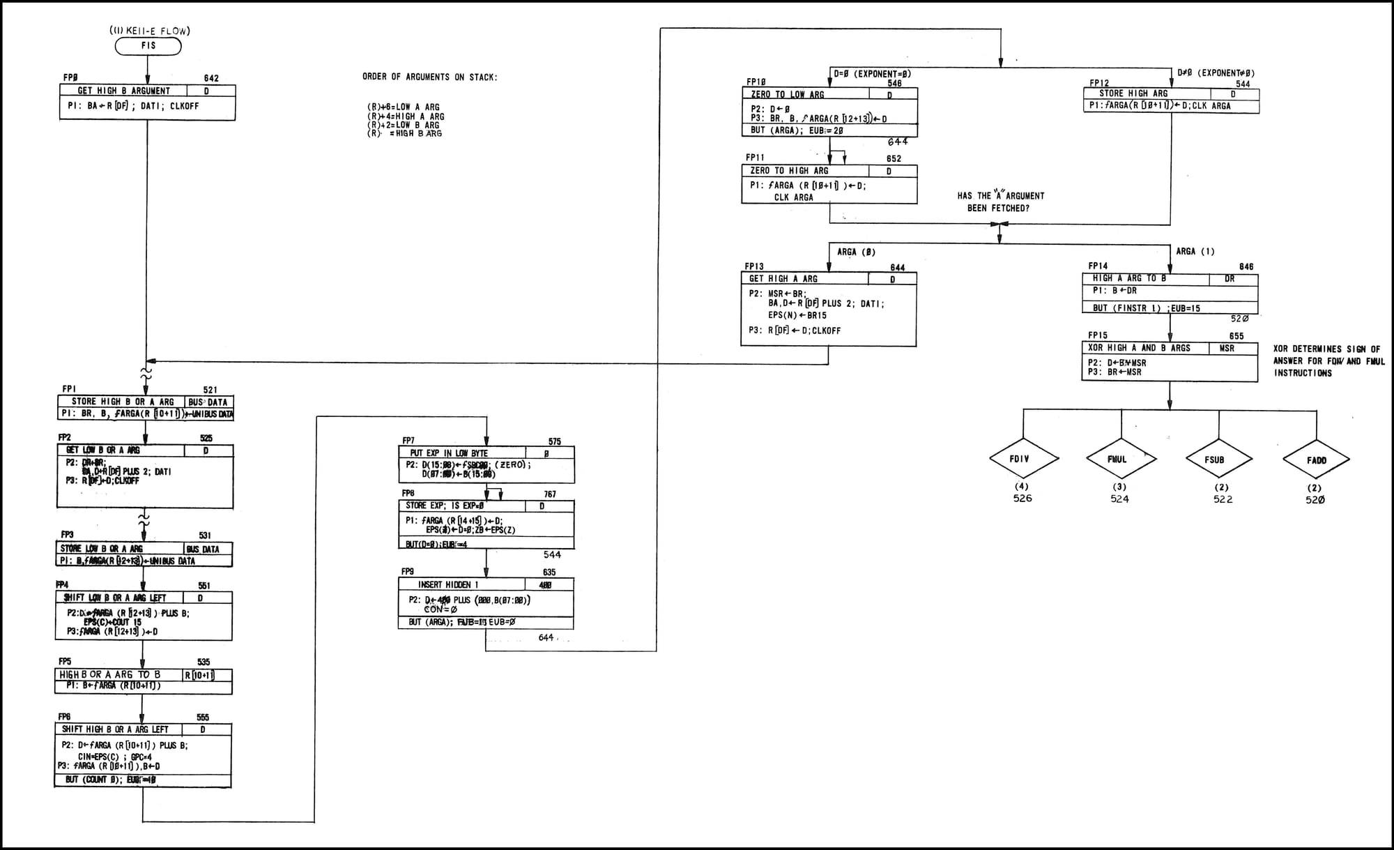
The above microcode flow is responsible for fetching and preparing the A and B arguments for later use in a floating-point operation.
At FP0 and FP2 the relevant address is loaded on the address bus, and an asynchronous bus transaction is triggered (DATI). On the completion of the bus transaction, the fetched data will be present on the data bus and can be processed by FP1 and FP2. The fault is occurring sometime during the FP0 or FP2 states.
Tracking Down The Fault
Now that we know the issue is the use of an invalid address, we have to work out where the address is coming from and its path onto the address bus.
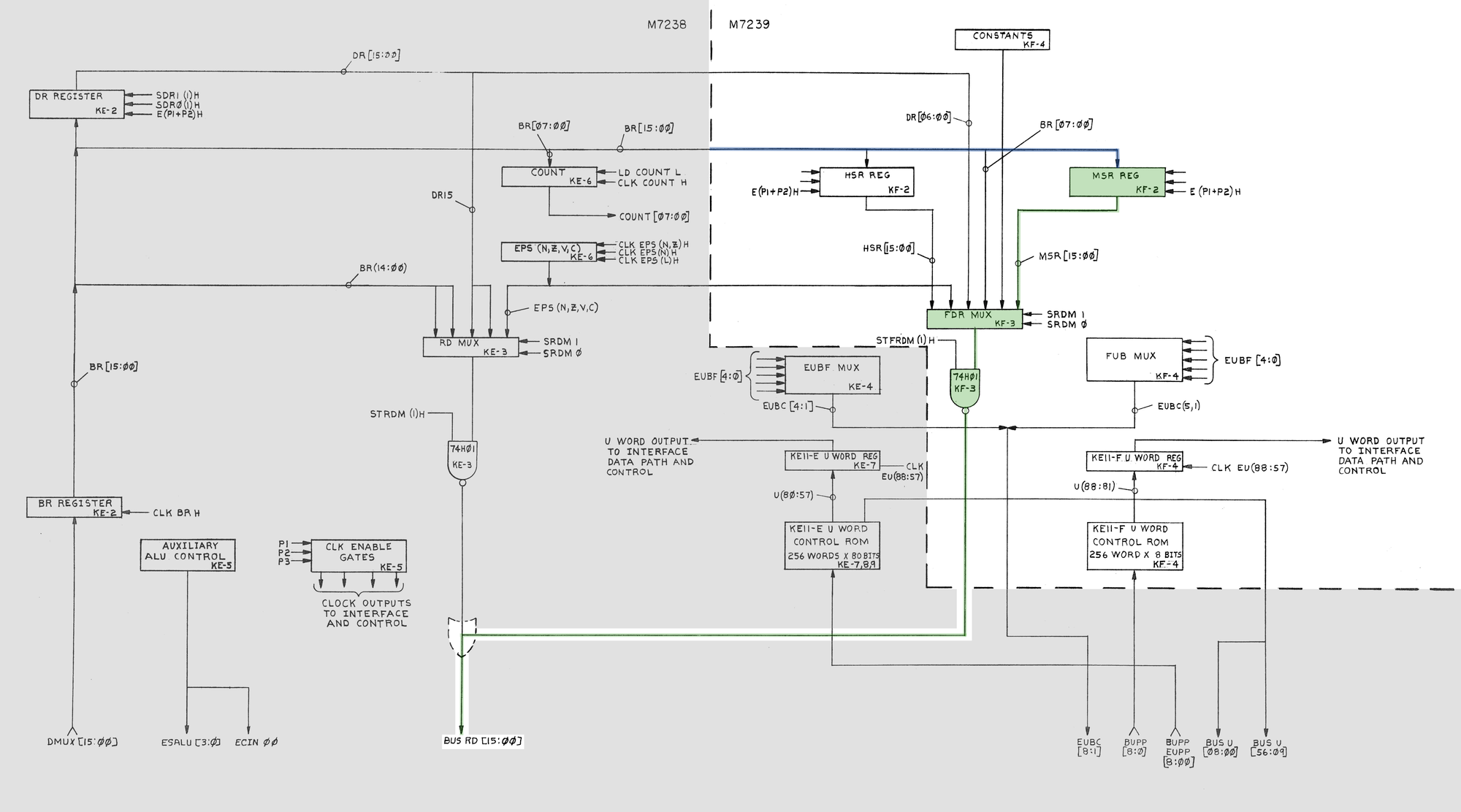
The address ultimately makes its way from the KE11-F to the processor address bus via BUS RD. Note that the above image shows both the FIS and EIS hardware; the EIS is working correctly.
Starting at BUS RD, working our way back up the bus, we find FDR MUX. According to the microcode listing, the select lines of the MUX (in states we are interested in) should be SRM0 = 0 & SRM1 = 0. I was able to verify this with the oscilloscope.
When SRM0 and SRM1 = 0, input A is selected via the MUX. Working our way back, we get to the MSR REG. We can assume that the input to the MSR REG (coming from the EIS) is good. I then spent some time comparing the input and output of the high bits that comprise the MSR register. I observed that while my probe was connected to the output pins, the stuck address bits would disappear or change.
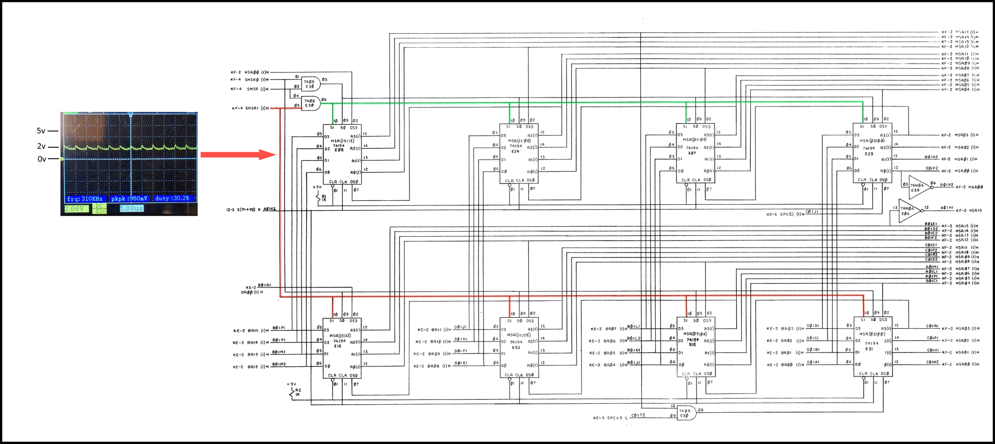
Doing a quick check of the pins that make up the MSR register, I found that SHSR1 was stuck at ~2V. Note that SHSR1 is only directly connected to the most significant byte of the MSR register. For the lower byte, SHSR1 goes through gate E30; this explains why only the top half of the address was affected.
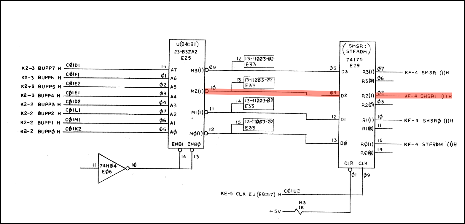
The bad SHSR1 signal comes from E29, a quad flip-flop (74175). Checking it, several of the outputs were stuck mid-rail.
The Fix
Replacing E29 resolved the address issues. The system can now run the diagnostics without crashing. However, it still fails the tests, see Part 2.