PDP-11 Floating Point Instruction Repair - Part 2

Last time we found and fixed a fault where the KE11-F was reading arguments from the wrong area of memory. That restored some basic functionality and allowed us to do some basic floating-point addition (1.0 + 1.0). Unfortunately, where we left off, the PDP-11 was still not passing the floating-point tests.
Narrowing Down the Problem
With the help of the diagnostic test, I was able to determine that floating-point addition is not completely functional. The next step was to try to identify some cases where it would work and where it didn't.
I created a simple test program to add two basic whole floating-point numbers together. I simply re-ran the same program over and over, changing the arguments each time.
I found that the following:
0 + 0 = 0
1 + 1 = 2
2 + 2= 4
2 + 1 = -12.9990234375
1 + 2 = -3.0146484375
As floating-point representation:
040300,000000 =   3.0          (1 10000001 10000000000000000000000)
140717,176000 = -12.9990234375 (1 10000011 10011111111110000000000)
140300,170000 = - 3.0146484375 (1 10000001 10000001111000000000000)
Curiously, adding a number to itself worked, but adding two different numbers didn't. Looking closely at the binary representation of the output, we can see that they are close to the correct answer; the exponent is mostly correct. The biggest issue is the sign bit and mantissa.
Further Narrowing
Now that we have a failure case, we can start working our way to the core of the issue. To start, I recorded the microcode flow (and data/address readout) for our fault case (that took a long time).
I inspected the microcode flow and found no obvious mis-branches. I then spent a day analysing the PDP-11/40 floating-point algorithm—but it was very complex, and I made little progress.
Changing tack, I decided to directly compare my functional KE11-F to the broken one. I sat down in front of the machine and slowly began stepping through the microcode, cross-referencing against previous microcode recordings. It did not take long to identify the problem.
Just after the microcode state FP9 and before FP12, the high part of the mantissa gets shown on the data display. The functional KE11-F showed 000400 while the broken board showed 100400!
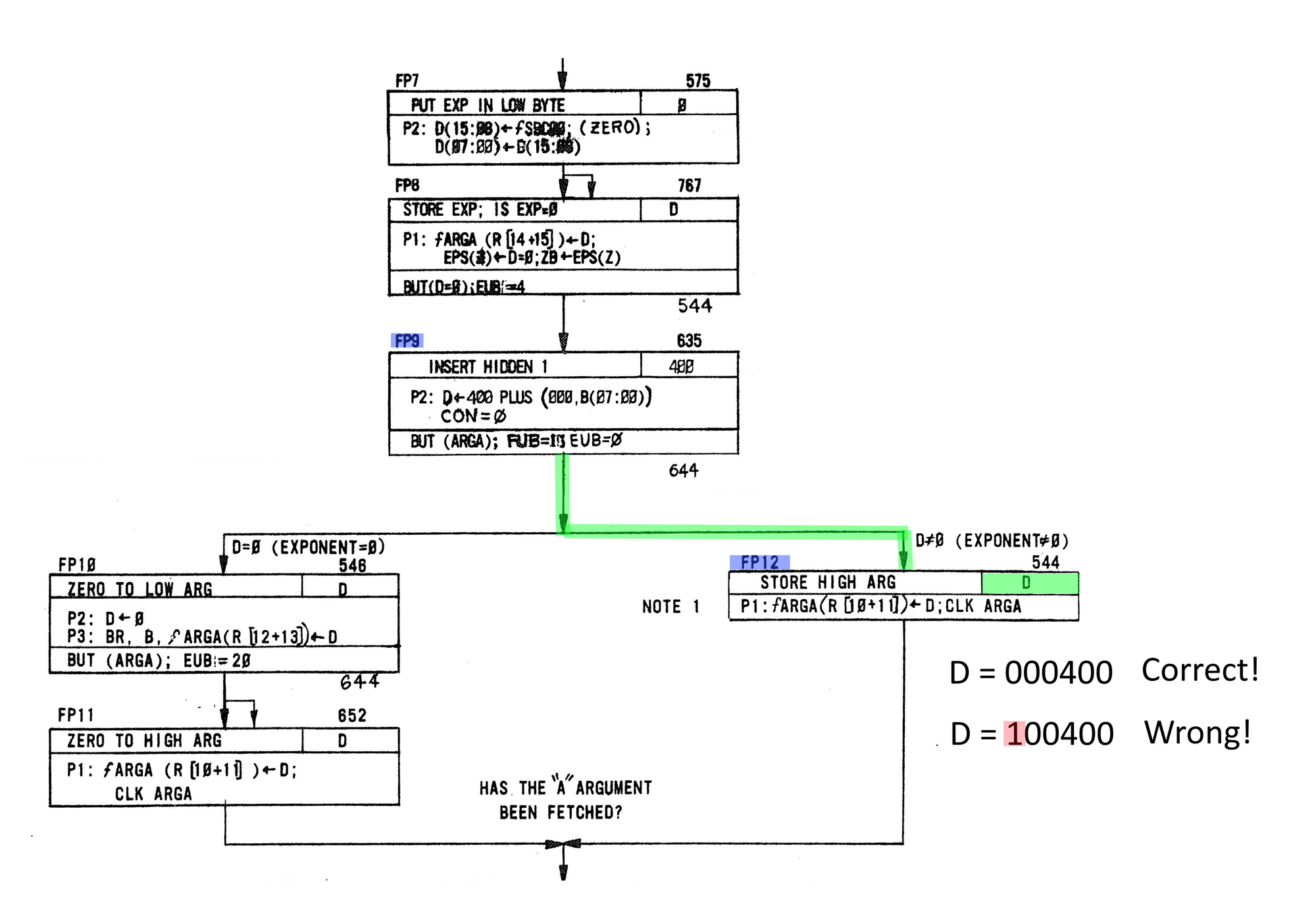
So, during the fetch and preparation of the floating-point arguments, an additional bit was getting set in the high portion of the mantissa, so the question is, how is the bit getting set?
Identifying the Hardware at Fault
If we look closely at FP9 we see that it's building up the mantissa from several component values.
Let's have a closer look at what is happening:
D 🠔 400 PLUS (000,B(07:00))

D 🠔 400 PLUS (0000000BBBBBBBBB)

D 🠔 (0000000BBB1BBBBB)
Here a 16-bit word is built up from the lower byte soted in B and zeros for the most significant byte, lastly 400 is added (100000).
However, on the faulty board we are ending up with the MSB getting set to one:
D 🠔 400 PLUS (000,B(07:00))

D 🠔 (1000000BBB1BBBBB)
      └── Incorrectly set!
Hardware
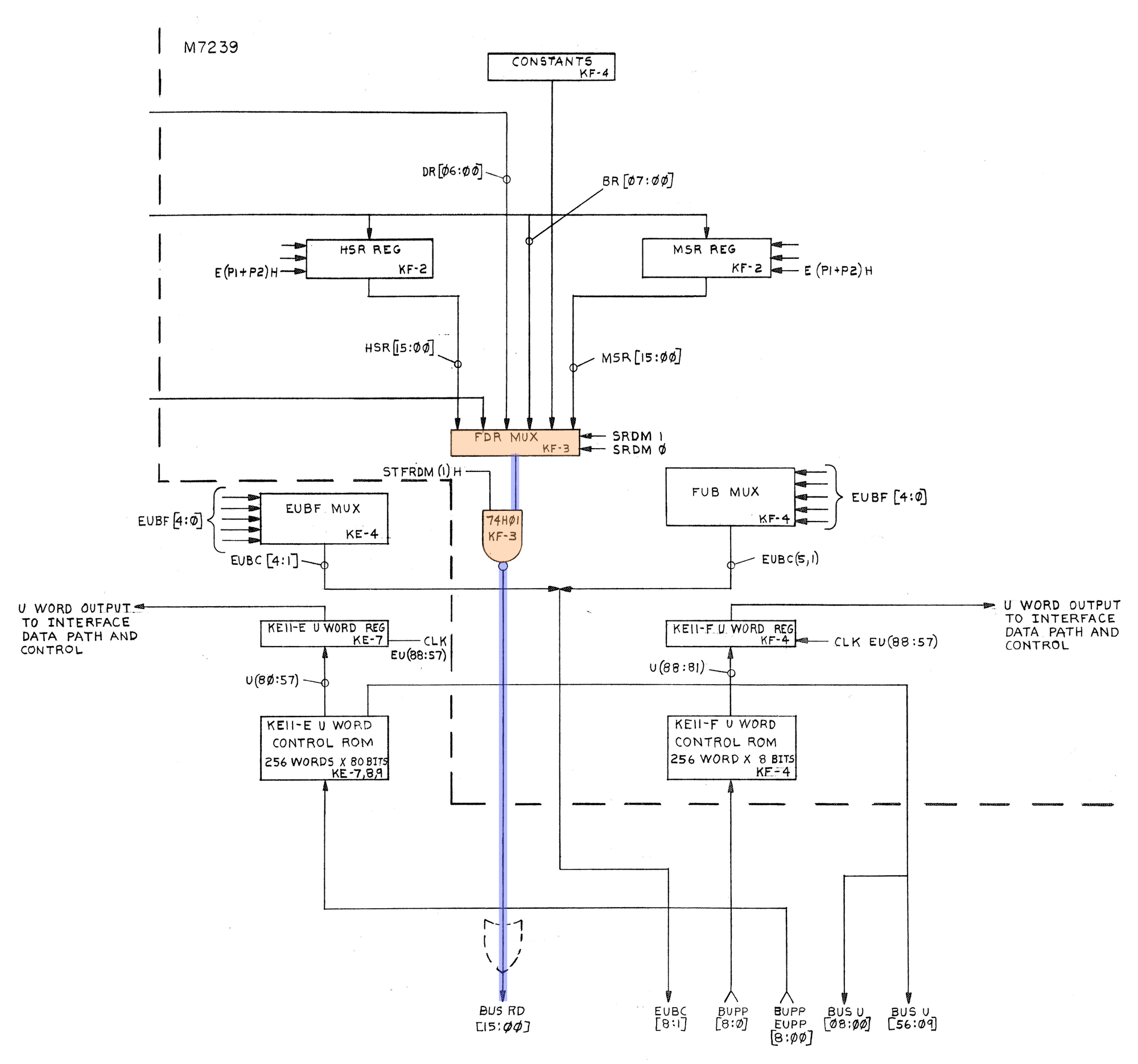
We know that for data to make its way into the D register, it has to make its way to the processor via the RD BUS. So it would be reasonable to assume that our failure is somewhere before it makes its way onto the RD BUS. Looking at the KE11-F block diagram, we can see that the RD BUS is fed by an open-collector driver and FDR MUX. To begin with, let's examine the bus driver and FDR MUX.
We know the KE11-F is trying to build a word that looks like this, 000,B(07:00). The only place in the KE11-F where this could possibly happen is the FDR mux, so the important question is, where do the zeros come from?
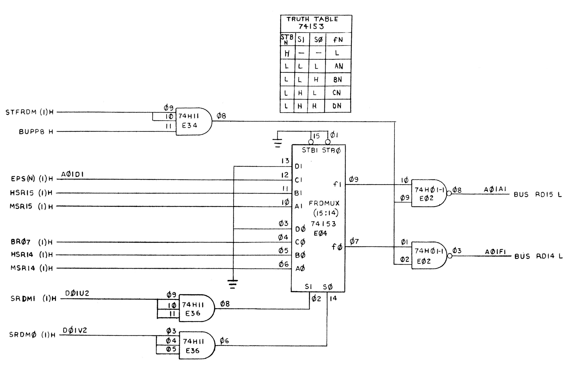
We could take an educated guess, but we can instead just check the microcode listing. The FDR mux select lines come from the microcode signals SRDM*, if we look up the value for SRDM during the FP9 state, we get 1,1. Comparing that to the conveniently provided truth table, we find that input D should be selected.
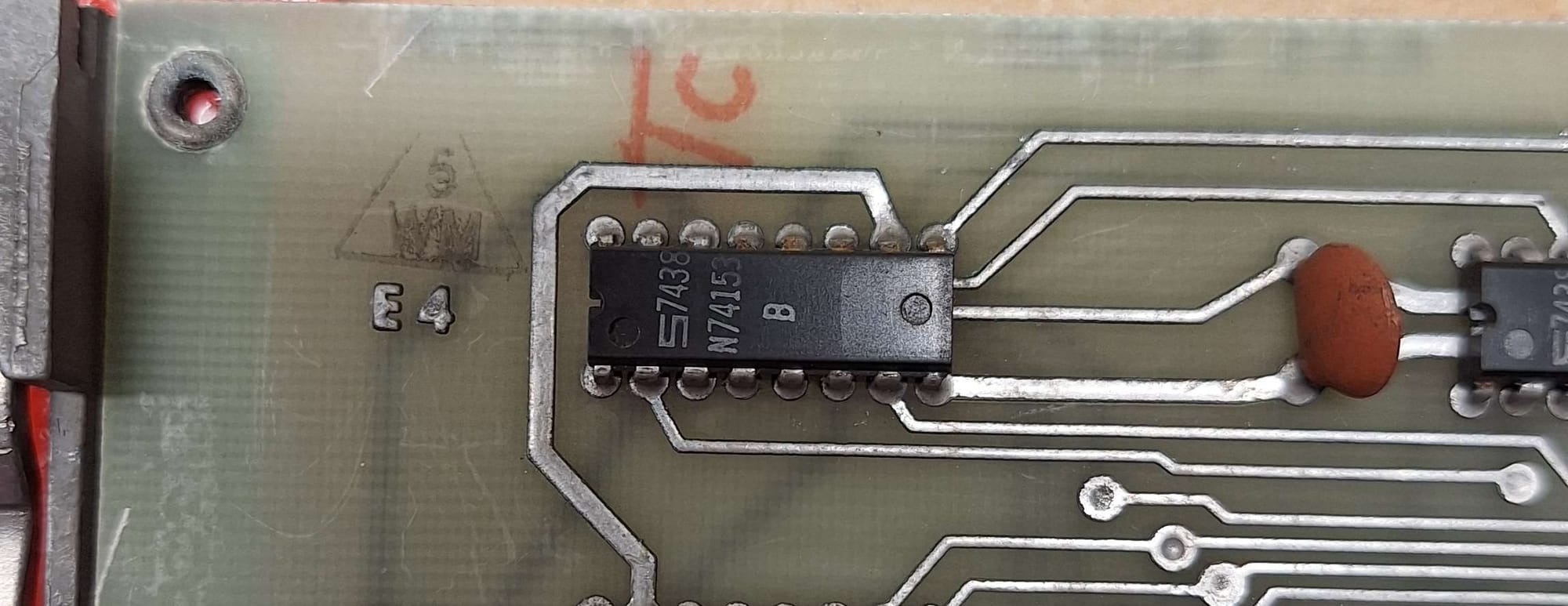
If we look closely at E04 (see the image above), we notice something interesting: both of its D inputs are tied directly to ground. This means that whenever the microcode selects those inputs, the expected output should always be logic 0. In fact, this is exactly where the octal constant 000 comes from.
Since we already knew a stray bit was appearing, this was the prime suspect. To confirm, I probed E04’s output with the oscilloscope. Sure enough, when the D inputs were selected, E04 produced a 1 instead of the expected 0. That was the verification we needed.
The conclusion was clear: E04, the 4-to-1 multiplexer, had failed. Replacing it brought the results back in line — the mantissa stayed clean, and the addition worked as expected.
Conclusion
This repair turned out to be a good reminder of how valuable it is to follow the evidence step by step. We identified that a rogue bit was showing up in the mantissa, and by narrowing down the possibilities, E04 quickly became the prime suspect. Confirming its failure with the oscilloscope made the fix straightforward — replace the chip, and the floating-point unit behaved as expected again.
It’s easy to underestimate how a single component can introduce subtle but serious errors. What looked at first like a complex microcode or algorithm problem was really just one faulty multiplexer.
With this issue resolved, the board can now handle basic floating-point addition reliably. There’s still more testing ahead, but this was a solid step forward in getting the KE11-F fully operational again.
Part 3 coming soon...