PDP-11 IR Decode Repair

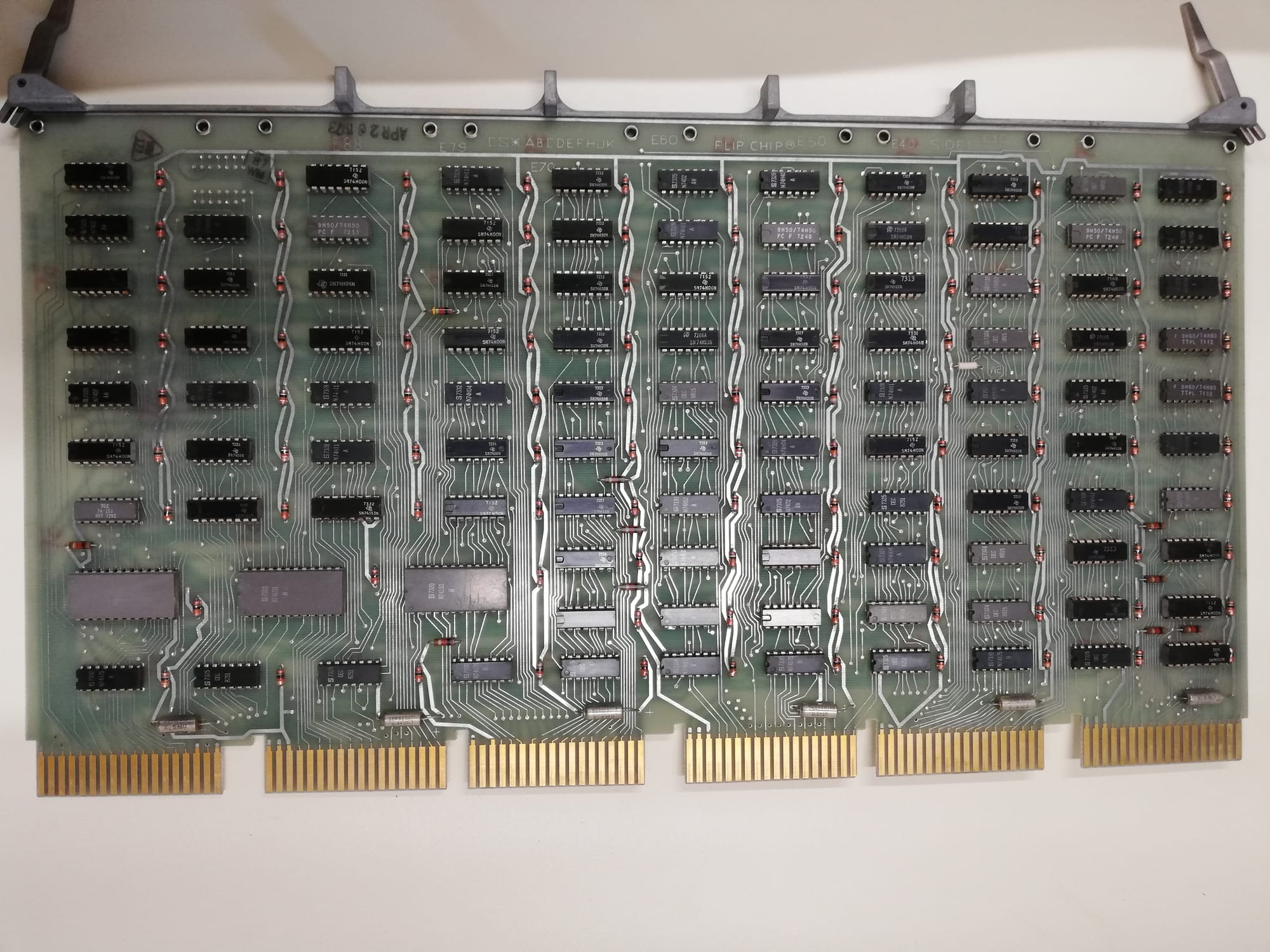
One of my two IR Decode boards would not boot the diagnostic software or pass basic tests.
Symptoms
When trying to run the bootstrap program to load the diagnostic from the emulated disk, the system would malfunction and would not boot. When loading and running the diagnostic software from memory via the unibone.
Specifically, the CPU was getting stuck on instructions like these: CMP (R0)+, R1, CMPB (R0), R1. In testing, I found that the instruction was not setting the expected processor status word (zero bit, carry bit, etc).
Debugging
The first step was to identify why the CMP (compare) instruction was not working correctly. Fortunately, the PDP-11/40 has a dedicated tool for examining the microcode routine, the KM11.
In a PDP-11, an instruction is performed over multiple clock cycles. The behaviour for each clock cycle is defined by the internal state of the processor and by a ROM, in essence, each instruction is a mini program. Essentially, the KM11 allows a technician to view the current and past "uProgramPointer" (UPP) of the executing "micro routine".
BUT Failure
By running the exact same instruction on both the good and bad boards, we may be able to find where in the micro routine the CMP instruction is failing.
Below is a list of the uProgramPointer addresses that were generated by the system while running the CMP instruction. On the fifth UPP you can see that there is an extra bit set, that bit is known as BUPP5.
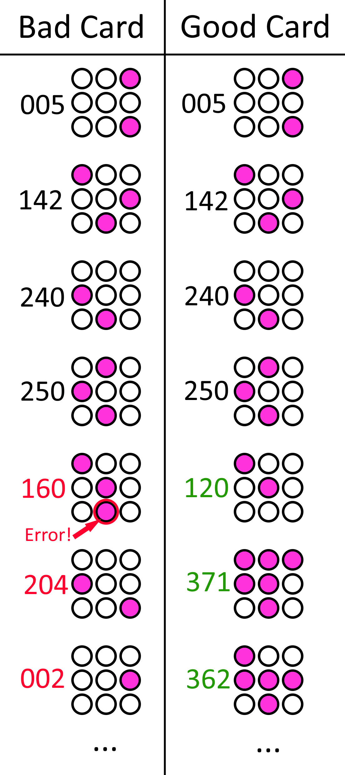
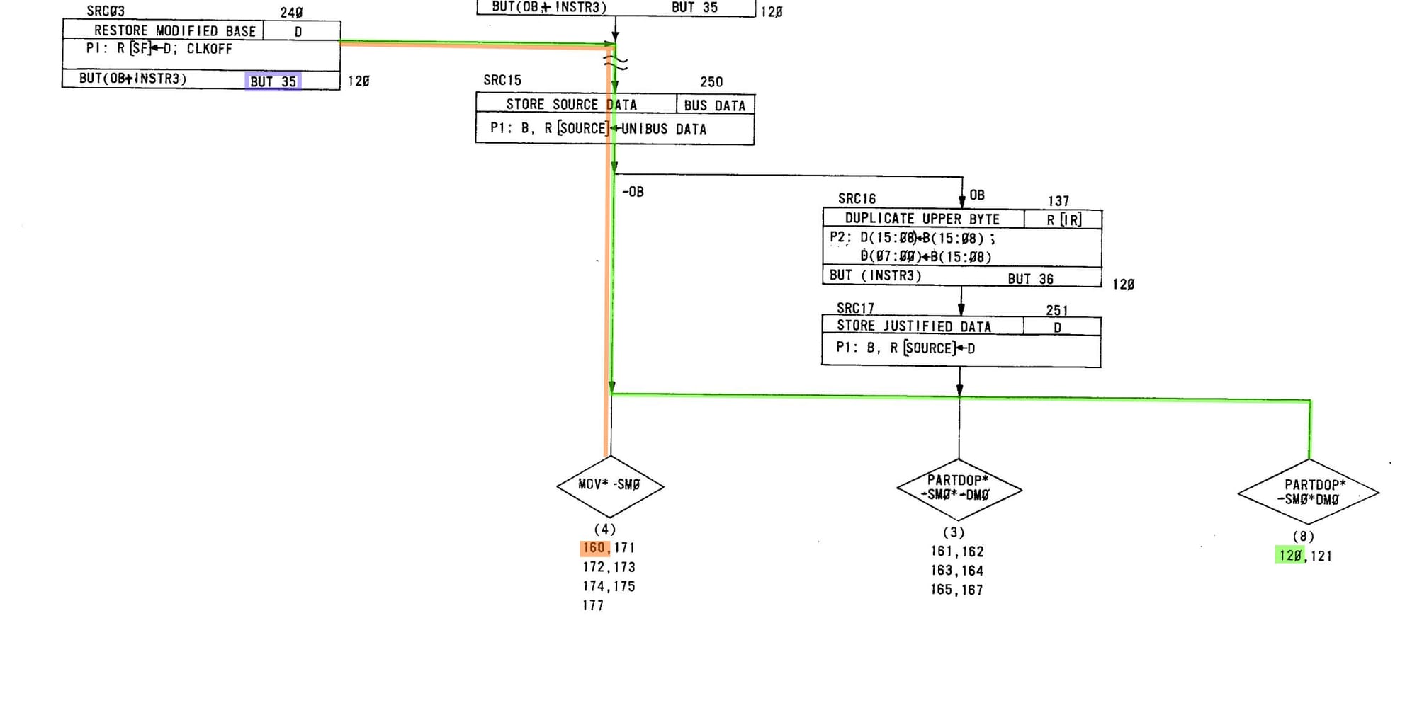
The correct microflow is meant to be 250->120->371, but my system had the microflow 250->160->204. The extra set bit, BUPP5, caused the system to incorrectly branch to 160 rather than 120. As it turns out, UPP 120 is part of the MOV microroutine, not CMP.
BUPP5 is set by what is known as a BUT (branch microcode test). Each BUT in the system is a collection of gates that evaluate various internal states to decide whether a particular condition is met. If we study the flow diagrams, you will see that the last BUT to happen before our miss-branch was BUT35; most likely the fault is in the BUT35 logic.
BUT35
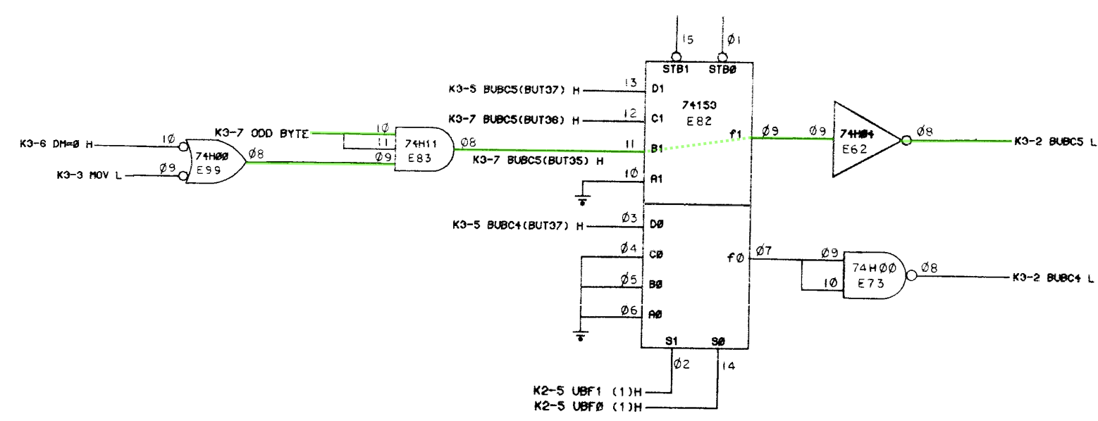
Below is a simplified schematic of the BUT35 circuit. Chip E82 (dual mux) is used to decide when a particular BUT is in use. The output, BUBC5, indirectly controls BUPP5. After about 1.5 days, I was able to identify that the chip E82 had failed, specifically when input 1 was selected, the output would become high, regardless of the state of BUBC35(BUT35).
The Fix
E82 (74153) has been removed. I am now waiting for a replacement to arrive from ebay.
Update
The repair was successful; the new chip fixed the IR Decode board.