RK05 Restoration

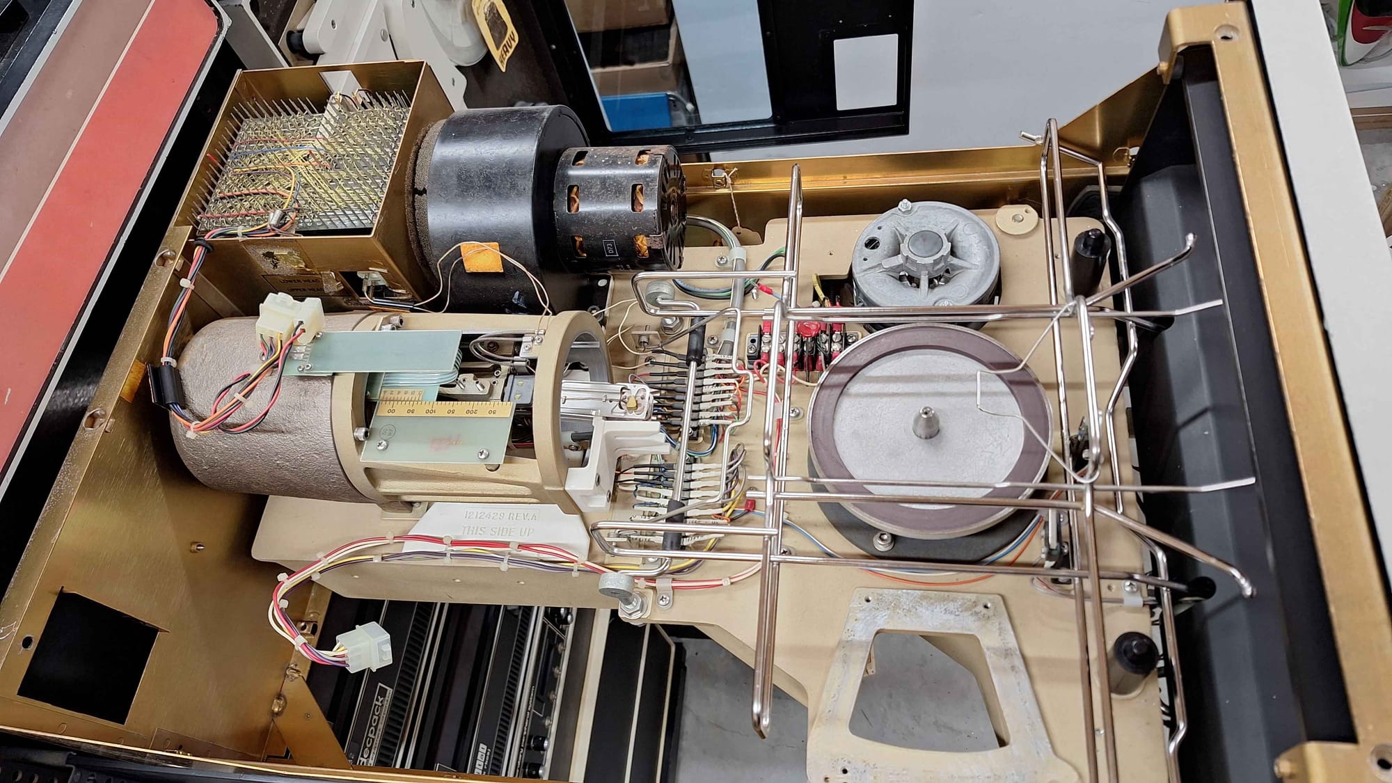
Here is a very quick list of things I have done and parts I have used for service my RK05 drives.
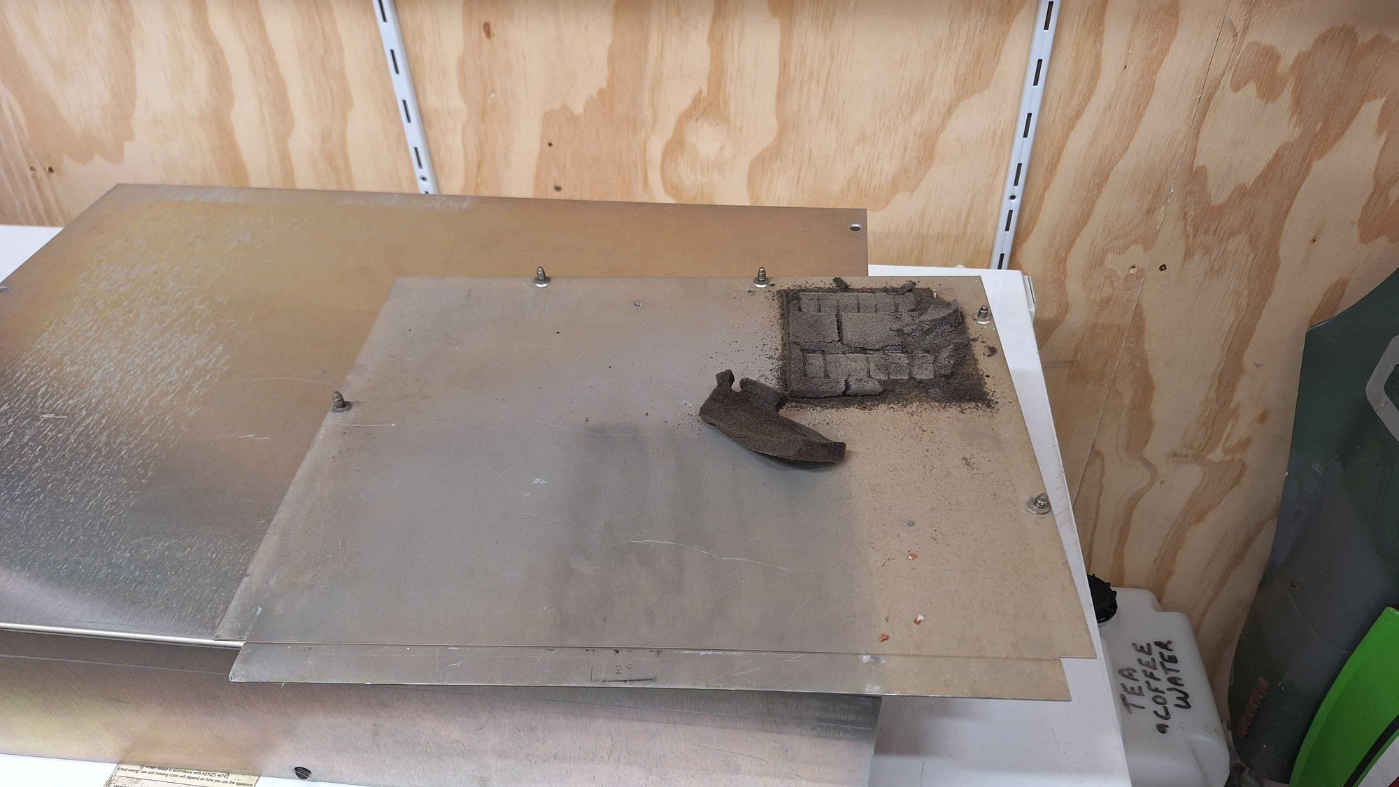
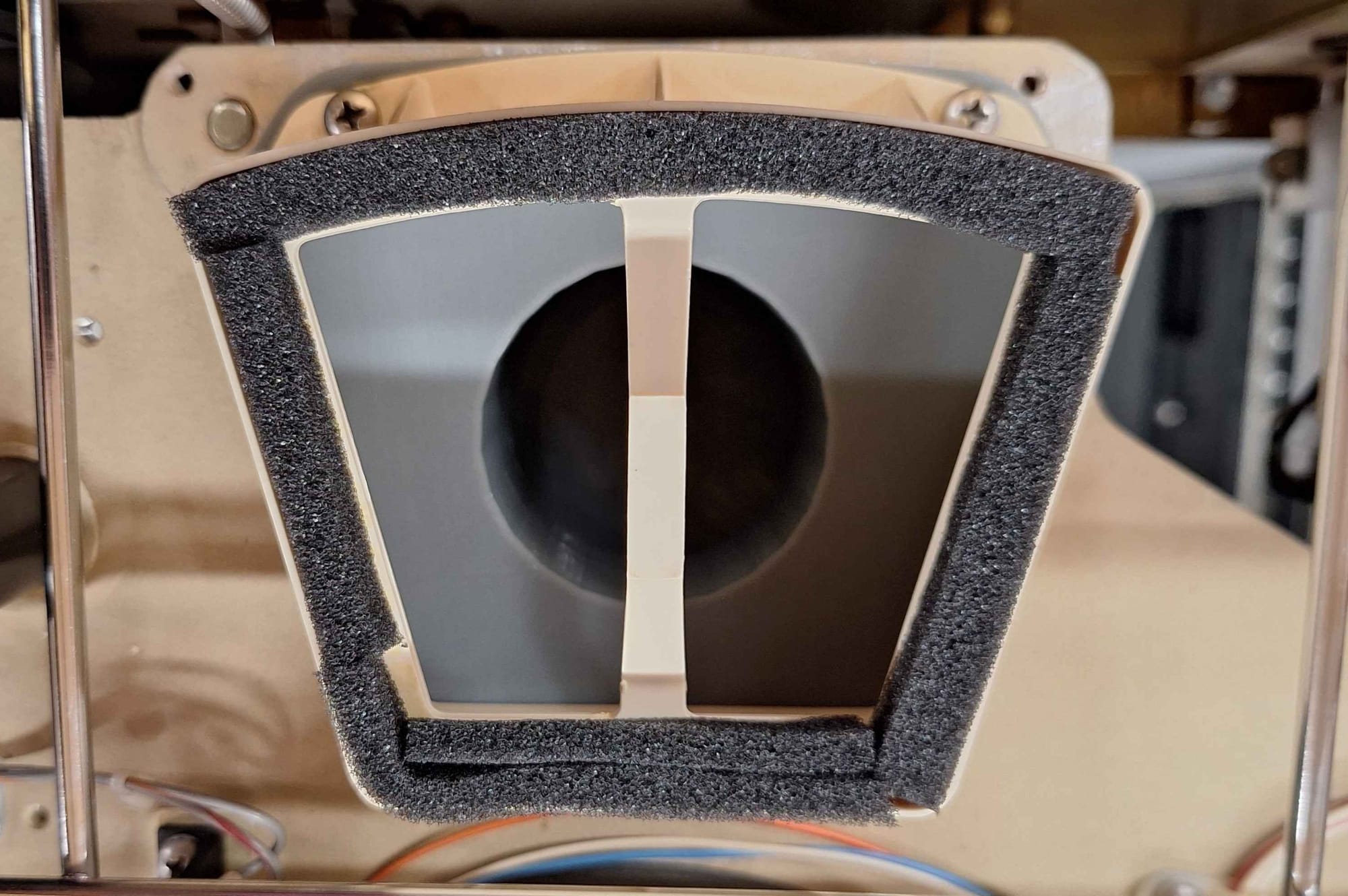
Replacement Foam
The first step is to thoroughly clean everything and remove and replace all of the old foam. For replacement foam you can use weather stripping material commonly available at hardware stores. The following foam needs to be replaced:
- Blower motor foam
- Disc pack seal foam
- Top lib seal foam
- Bottom seal foam
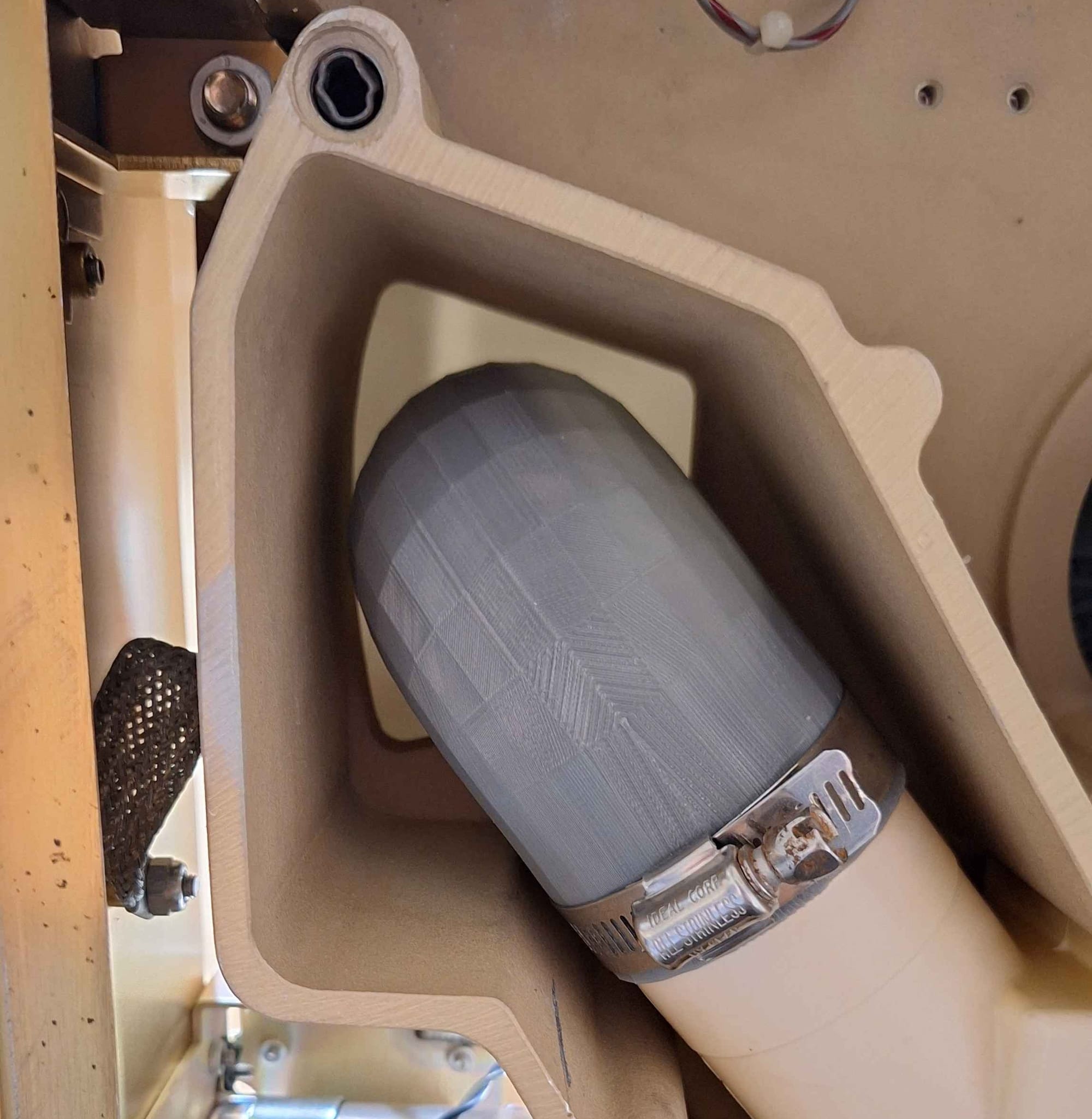
Rubber Hose
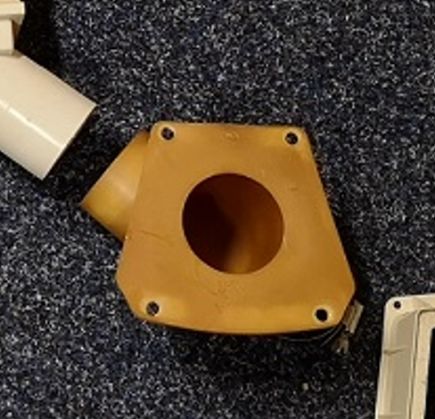
There is a rubber hose that connects between the filter and the disk pack inlet. You may need to replace this if it's falling apart. I had JLCPCB print a replacement from TPU and PEBA. The STL file can be found here: https://so-much-stuff.com/pdp8/cad/3d.php
After doing some testing the TPU version is better. It holds it shape better and prints much better as well. JLCPCB did a good job.
Capacitor Replacements
The regulator modules use large 50v 900uf axial capacitors. Apparently these go bad and should be replaced on site. Replacements, 1000 uF, 63 VDC Vishay Axial, 1.3 A RC.
The PSU also has some large filter caps.
6800 uF, 100 VDC, 51*80mm
6800 uF,63 VDC, 36*62mm
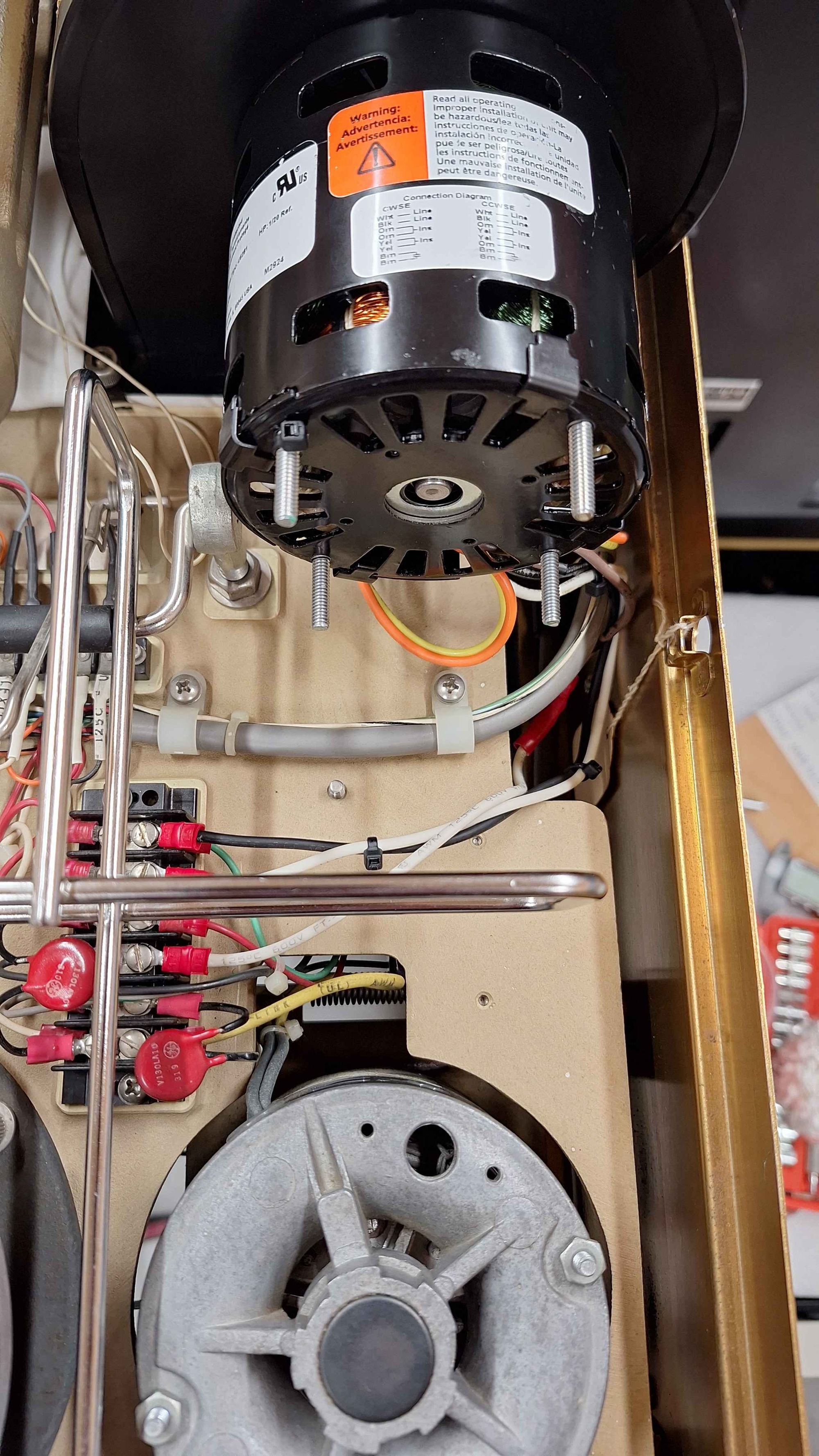
Blower Motor Replacement
One of drives needed a new blower motor. After a day of searching I found a new replacment part that meet the specifications of the original and is an allmost perfect replacement - Dayton 6NZP6A. I have been using the 60hz version on 50hz without and issues.
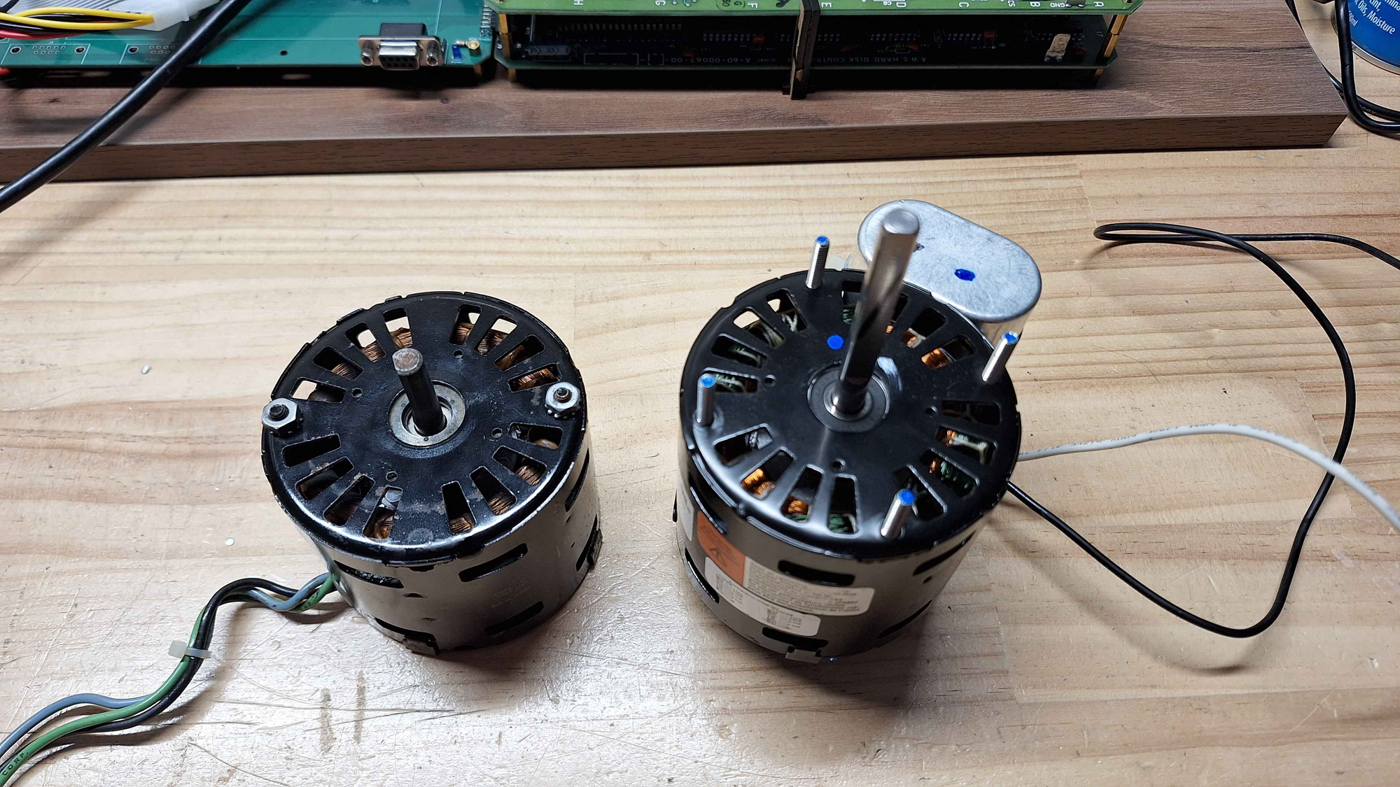
Installation
The new Dayton's shaft is a lot longer then the original, fortunately it does not get in the way and can be left alone. Unfortunately that is not the case for the mounting the studs, you will need to cut them down with a hacksaw.
Next the capacitor needs to be moved, no matter the orientation it gets in the way and there is insufficient space to get the case closed. Additionally the new capacitor is a lot shorter than the original, so I would recommend using the original capacitor. In my case both the original and replacment were both 370v 5uf, so there were no issues.
Wiring
You will notice that the you will notice that motor has three wires and the replacment has four (two live, two capacitor). One of the capacitors leads is connected in parallel to one of the live cables, on the original motor this was done on the terminal block while the new motor this is done as part of the winding.
One of the two brown capacitor wires will have a 0ohm connection to one of the live wires (black), you can cut this cable off, as you will not need it - remember to insulate it!
The live wire that has the 0ohm connection to one of the capacitors (black), that is the same as our green wire - live and connected to the capacitor.
The second live wire (white) is the same as the blue wire.
The remaining brown wire is the other connection to the capacitor.
Trim the wires down to the appropriate length, use some of the offcut to extend the length of the the brown wire and terminate them as needed.