TV Composite Mods
A very crude guide for modding old TVs to accept composite video inputs. Also a list of chip and how to mod them.
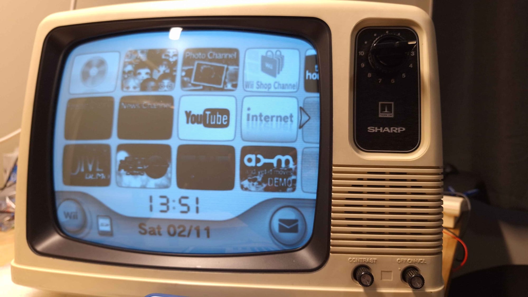
General information about adding Composite Mods to various 80s TVs.
General Technique
Most composite mods are done by identifying the unmodulated video signal and injecting a suitable composite video signal. Many TVs from the 80s use a single chip to do all the RF demodulation, these sets are the easiest to modify especially if data sheets are available.
Identifying the Video Signal From the Data Sheet
The first thing to do is to find where you need to inject your composite video signal.
Start by searching the board for chips, sometimes they are hidden under RF shielding, so you may need to remove some. Do some research and see if you can find any datasheets. If you get lucky you will find one.
Example chip
Here is the AN5151N it's often found inside portable TVs, it's a single chip that manages everything. The area that is relevant to us is pin 5, you can see that it's ultimately connected to a transistor that is driving a signal named Video Output. This is the signal we need to replace with our own.
In this situation, we can simply cut the trace conceded to pin 5 and replace it with our composite video signal. Pin 5 should be disconnected and our signal will be conceded in its place.
Identifying the Video Signal By Hand
If you find that you can't get the datasheet or schematics the next thing is to examine the output of the chips.
Start with the chip with the largest physical package, this will most likely be the one you are looking for. Connect your oscilloscope's ground to the RF ground and very carefully take a look at each pin.
If you are running the TV without a RF signal you want to keep an eye out for a signal that contains a large amount of typically with an amplitude between 1-2 volts.

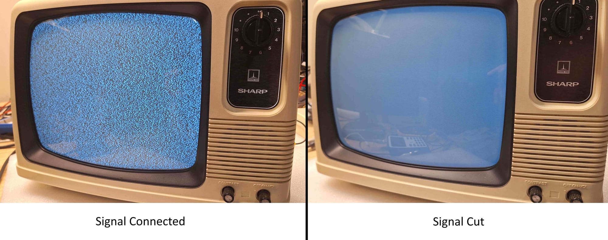
Once you think you have found the right signal there are two ways to validate it. The first way is to connect a valid RF video signal and check the signal, if you are right you should see a signal that approximately resembles a composite video. The second method is to cut the trace, if you have the right signal the snow on the screen should disappear and the screen should become blank.
Matching Signal Levels
With the appropriate signal identified we need to ensure that the voltage levels of our composite video signal match the one we a replacing.
Typically composite video is in the range of 0v to 2v. As most of these older TVs are analogue and they are tolerant to out-of-spec video signals, this makes our job much easier.
Example Shifted Signal
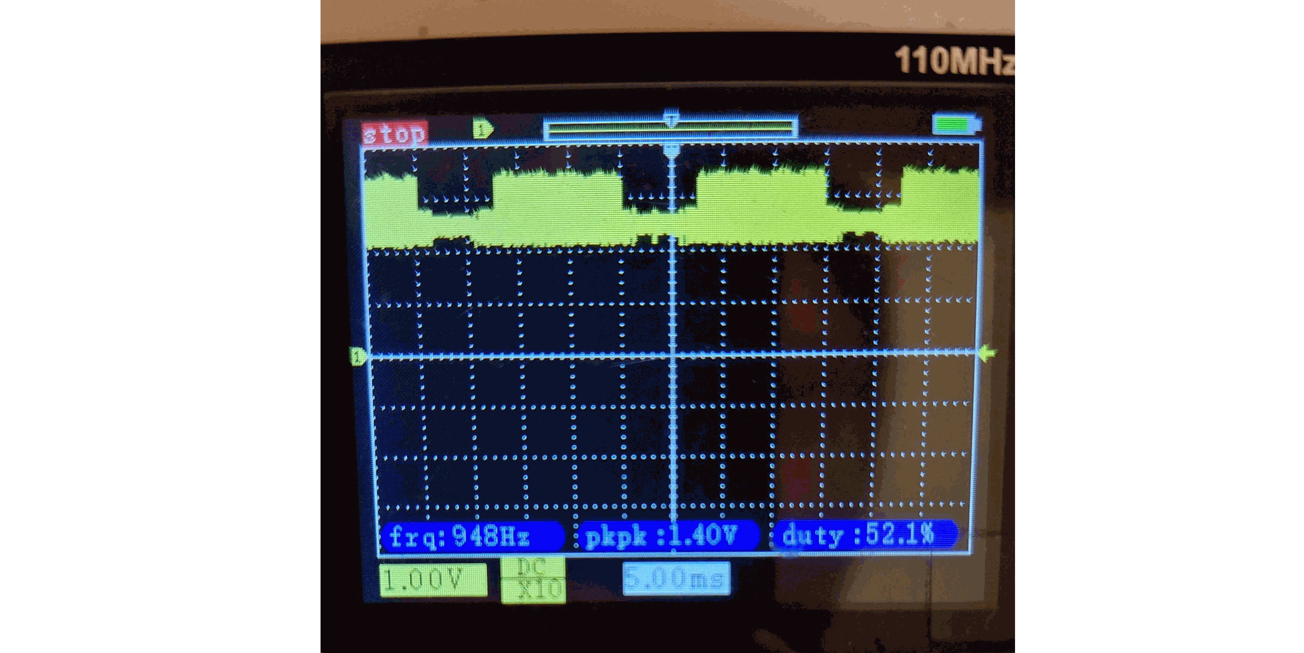
The above image is taken from a TV set that added a 2-volt shift to the demodulated video signal. If you were to just replace the signal directly with composite you may find that it does not work properly (might not sync or may have unusual artefacts).
To ensure things work we need to shift our video signal up by 2 volts. Fortunately, we can do this with a simple voltage divider that only uses a few passive components. You can either build the voltage divider with resistance values appropriate for your situation or use a single potentiometer and adjust the value by hand.

You will need to identify an appropriate power source for the voltage divider. Generally, the power rail used by the main chip is suitable. The optional capacitor can help to remove high-frequency jitter if you experience that problem.
Portable TVs
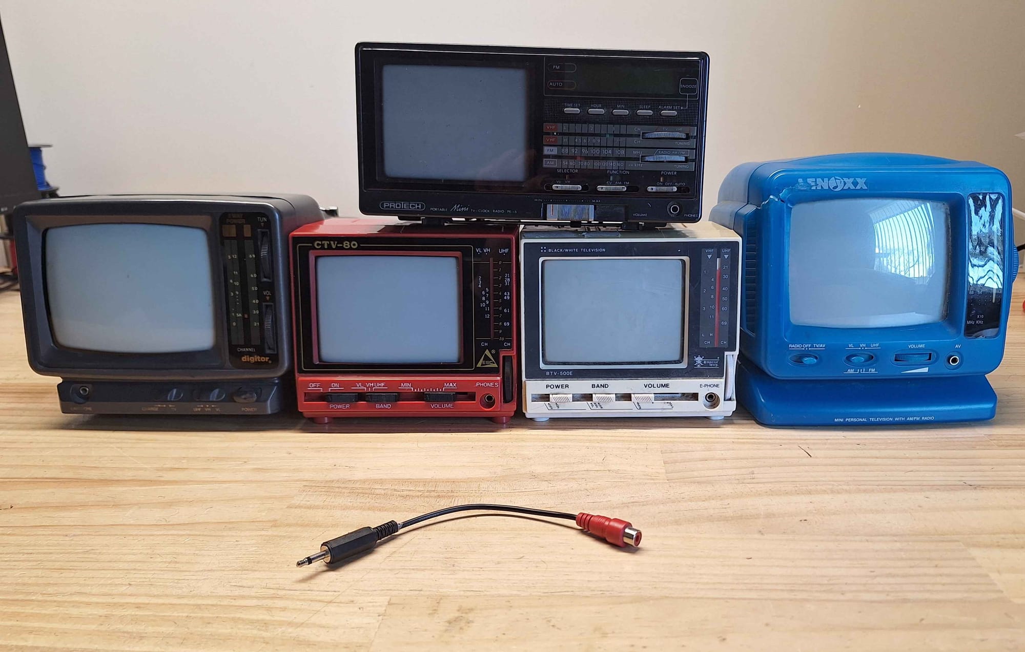
These little TVs typically use a single chip and you can just directly modify them to accept composite without needing to do any level shifting.
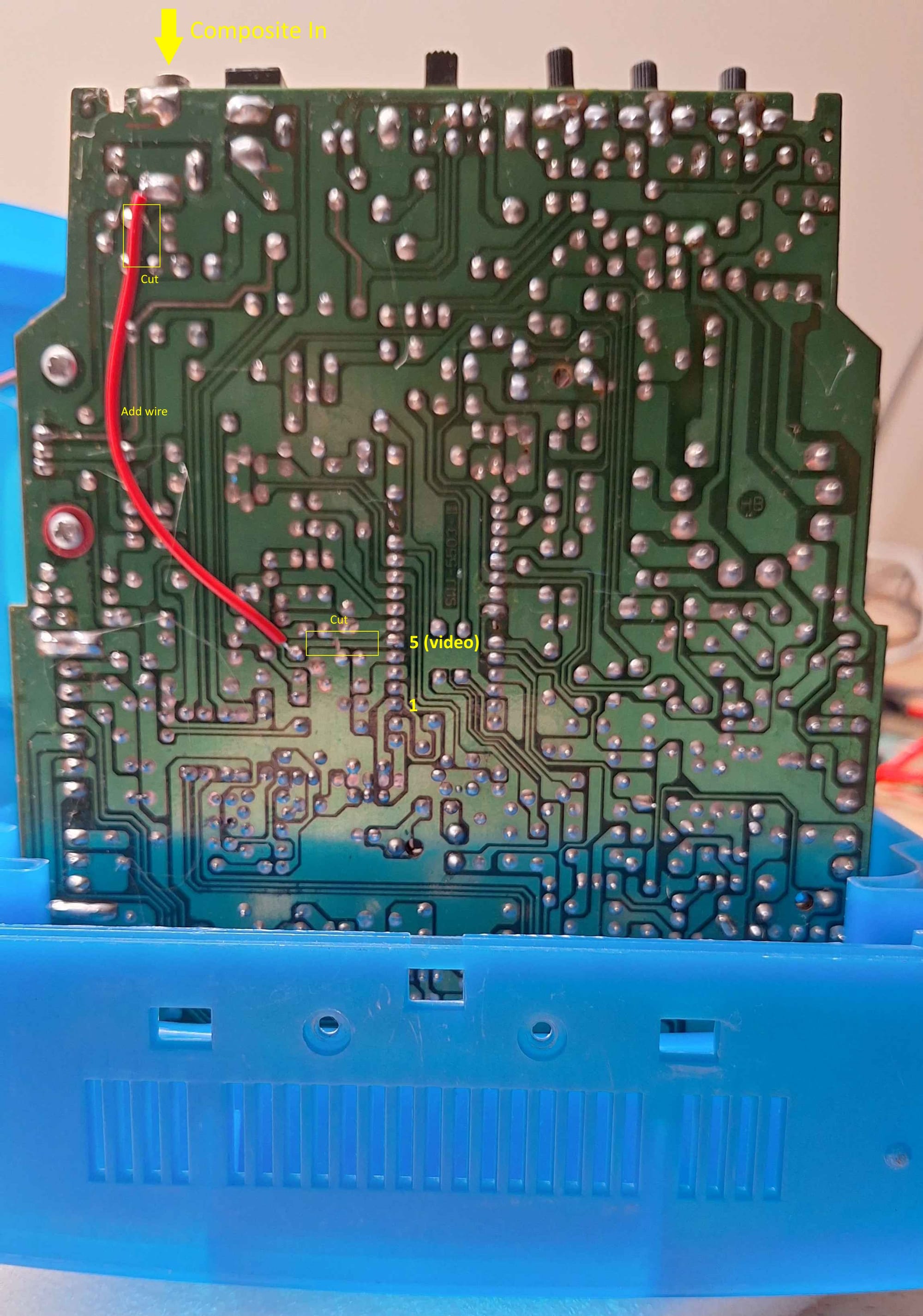
I like to modify these little TVs so that I can feed in composite video via the old external antenna connection, above is an example of how I've done so with a TV that uses a PJ2915CD chip. Then I just make a simple adaptor cable.
Thorn/Sharp Model 1202 BW TV
There are at least two variances of the 1202. Both use identical cases but have completely different innards. The information below focuses on the model that uses the SHARP X0100A.
The 1202 is an example of a TV that requires the video signals to be shifted up. I built a simple voltage divider circuit to shift the signal by about 2.5 volts. It was also necessary to add a 390pf capacitor between Video and Ground to prevent the screen from jittering.

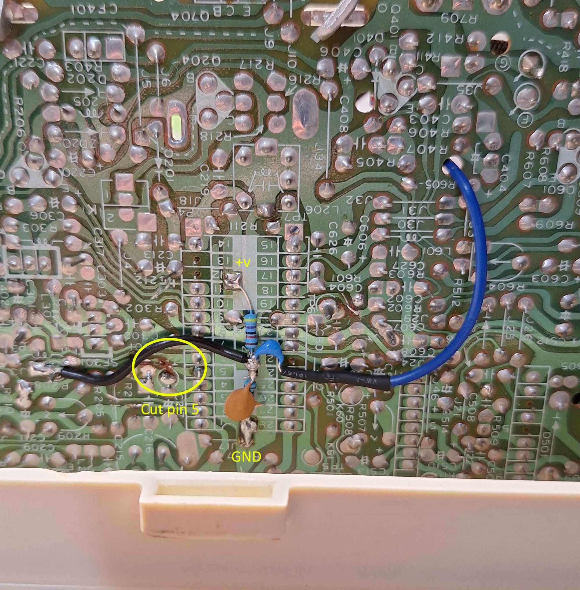
the modification can be done rather easily, simply build the above circuit and install it on the underside of the board. In this case, the injected composite video signal is the blue wire. I would recommend using a shielded cable for the best possible result. On this modification, I did not and I have come to regret it.
Known Chips and Mods
Here are some of the chips I have seen and what you need to do to mod them. Note that when I group various chips together you can only rely on them being similar but not necessarily identical.
PJ2915CD, CD5151CP, AN5151N
AN5151N Application - Cut pin 5, inject composite video
LA7507, KA2913A
KA2913A Application - Cut pin 12, inject composite video
SHARP X0100A
Cut pin 5 and inject composite video with level shift. Use a nearby power (9-12v).

