PDP-11 Floating Point Instruction Repair - Part 4
Back at it again — working on another issue with the FIS. The twist this time? It passes all the tests…

Back at it again — working on another issue with the FIS. The twist this time? It passes all the tests…
Symptoms
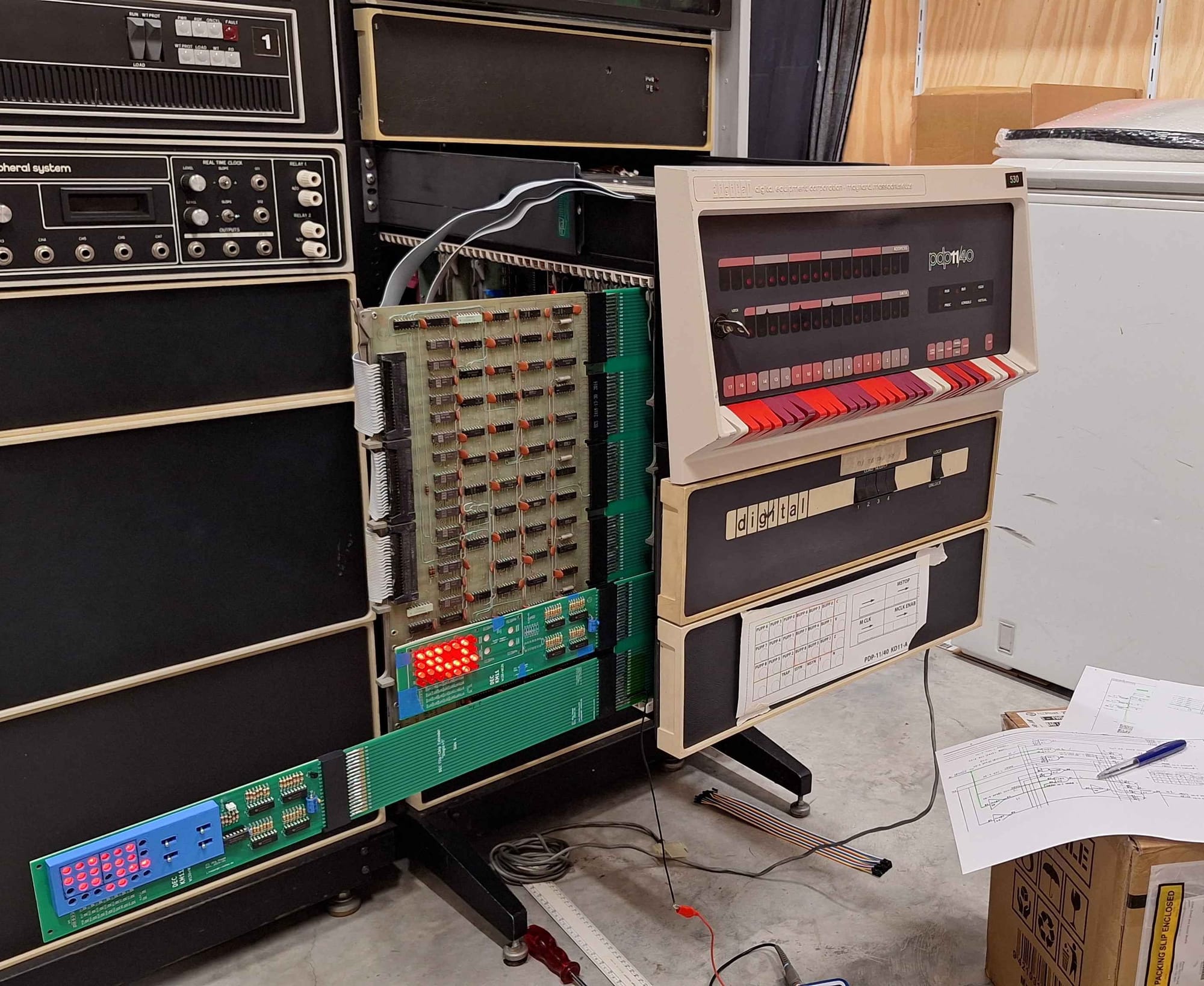
This all started when I tried to boot Unix V6. The Unix kernel is launched from the bootloader via command line. When I entered the boot command, there was a flash of lights — then nothing. I was dropped straight back to the bootloader prompt with no progress.
In a panic, I started swapping boards to get the machine back to a state where it could boot Unix. After trying every board, I was able to narrow the fault down to the FIS board — so some progress at least.
Next, I needed to figure out exactly what's wrong — so I ran the diagnostics. Nothing. It passed all the tests without issue! Since the FIS relies on the EIS for many functions, the next logical step was to check the EIS.
When testing the EIS, it passed the first three tests, but failed on the multiply and divide instructions. Very interesting… Specifically, the EIS seemed to think that 0x1 == 177777!?
Debugging
We know the EIS and FIS are interconnected, so it’s entirely possible the faulty FIS board is interfering with the EIS. At this stage, though, we don’t have evidence to confirm that. Let’s start with what we do know: the EIS thinks 0x1 == 177777.
The first step was to step through the relevant microcode and verify the CPU was following the correct path — with no mis-branches or other malfunctions. I confirmed the flow was indeed correct.
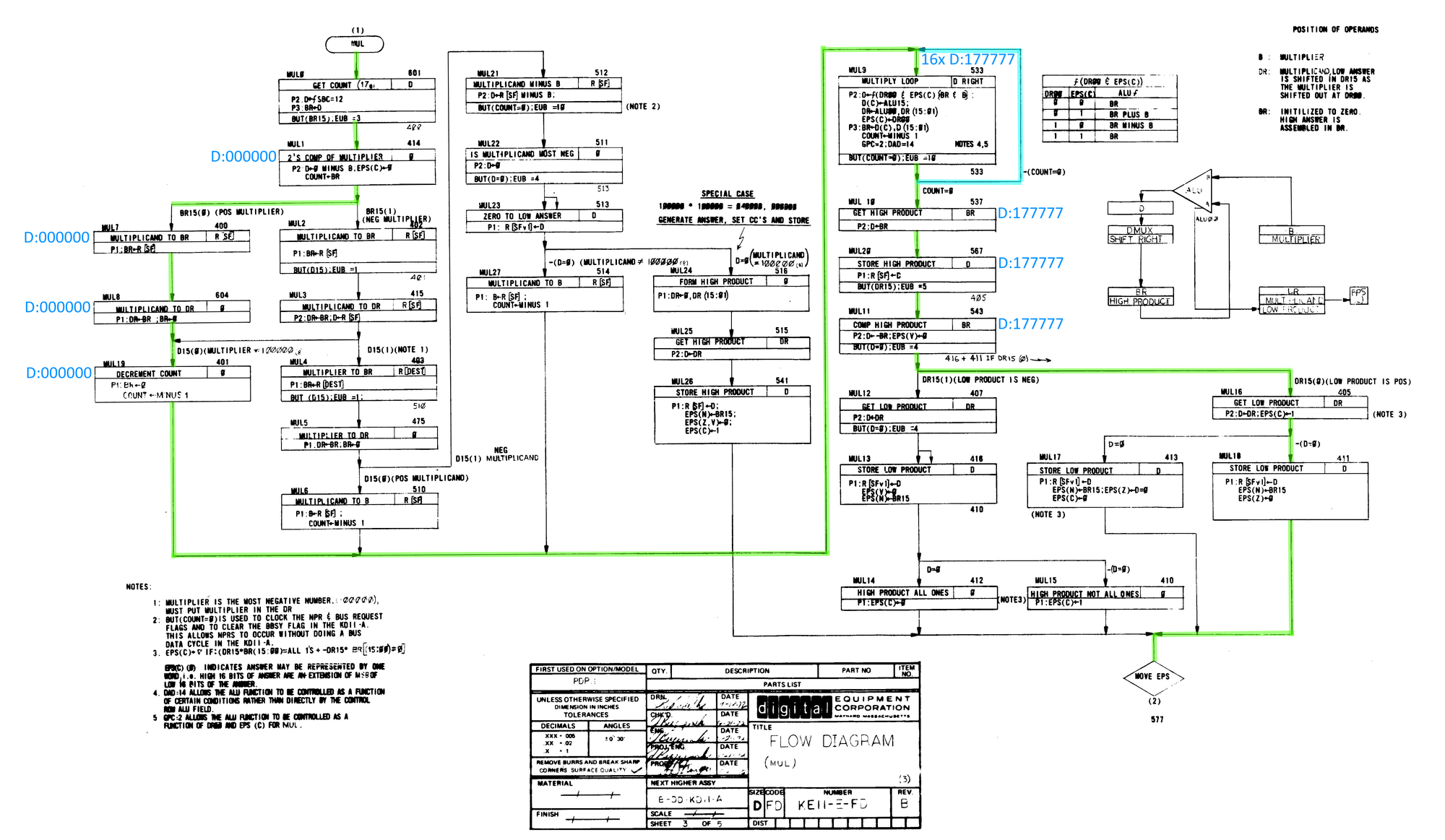
Next, I repeated the exercise while observing the data LEDs. At first everything looked normal, but as soon as the multiply loop began, the incorrect result appeared. The multiply loop runs 16 times — and after each iteration, 177777 was displayed. When the loop finished, the final value was still 177777.
So why do we get 177777 on the first iteration and why do does it not change over multiple loops? The answer to that is complex and is specific to how the PDP-11 does multiplication.
PDP-11 Multiplication
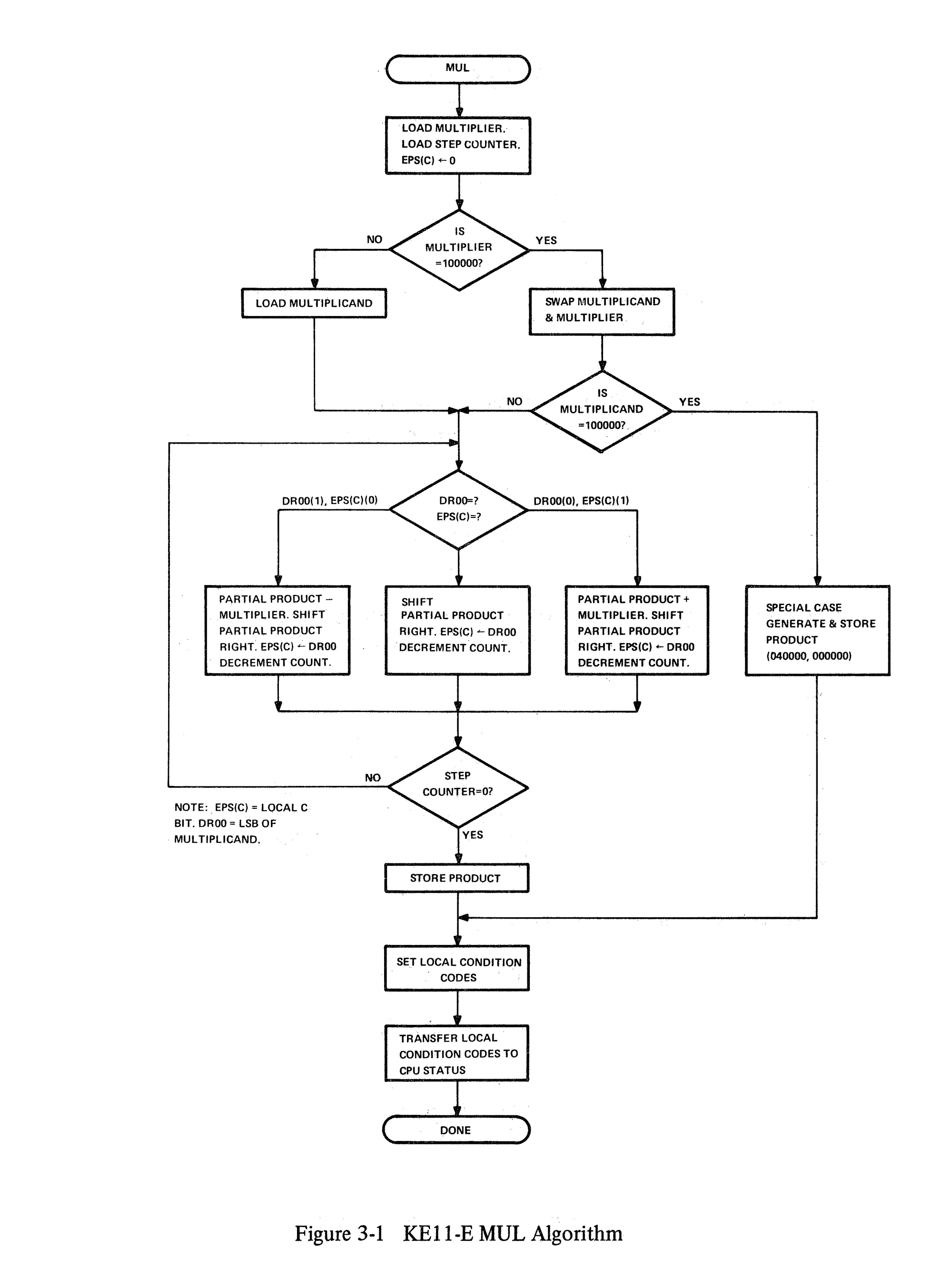
The EIS implements multiplication using Booth’s multiplication algorithm, which allows signed two’s-complement multiplication to be performed using only shifts, adds, and subtracts. Rather than treating the multiplier as a simple sequence of bits, Booth’s algorithm examines the multiplier one bit at a time along with the previous bit, and decides whether the multiplicand should be added, subtracted, or ignored on each iteration.
Internally, the EIS performs multiplication as a 16-cycle iterative process. On each cycle:
- The current multiplier bit and the previous bit are examined
- Based on that pair, the ALU is commanded to:
- add the multiplicand,
- subtract the multiplicand,
- or do nothing
- The combined accumulator and multiplier register is then shifted right
The EIS does not compute a product in one step; instead, it builds the result progressively across all 16 iterations.
Multiply Loop
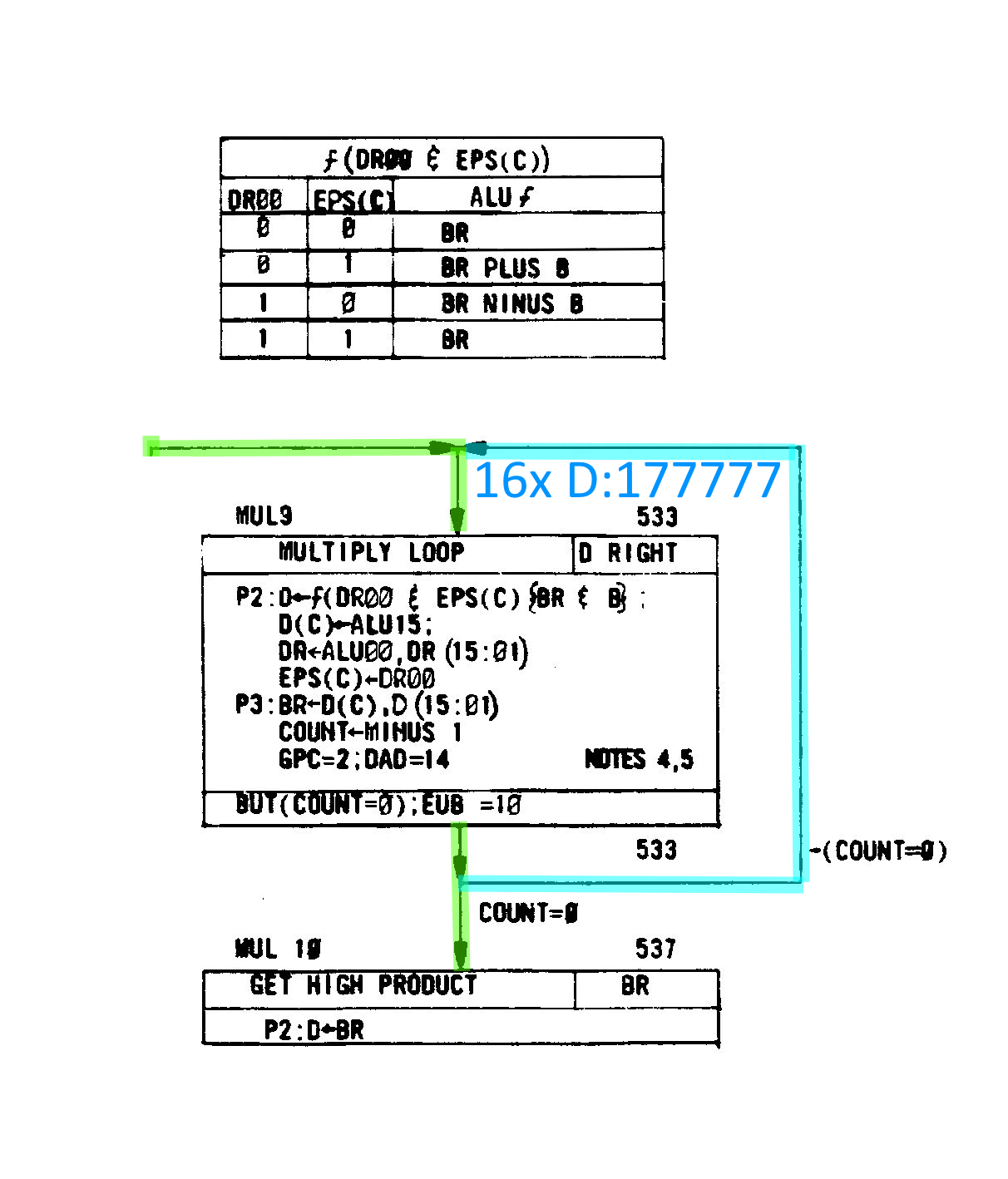
Once the multiply flow is entered, the EIS executes a tight 16-cycle loop that applies Booth’s algorithm one bit at a time. Each iteration examines the current multiplier bit together with the previous bit, uses that pair to select the ALU function (add, subtract, or no operation), and then performs an arithmetic right shift of the combined accumulator and multiplier registers. Apart from the ALU operation itself, this loop is highly regular: the same sequence of micro-operations repeats on every pass, with only the ALU control inputs changing from iteration to iteration.
In our case, the important micro-operation is:
D ← ƒ(DR00 & EPS(C)) { BR & B }
This line describes how the ALU operation for each multiply-loop iteration is selected. The function ƒ(…) is chosen by the logical combination of DR00 and the EPS(C) (extended processor status carry) bit, and that function is then applied to the BR and B registers. The result of that ALU operation is written into the D register. The table below shows how each combination of DR00 and EPS(C) selects a specific ALU operation.
Example 0 x 1 = 0
Let's take the example of 0x1. Here is the initial state:
ESP(C) = 0 (Default value, set in MUL1)
DR = 0 (From 0 x 1)
B = 1 (From 0 x 1)
DR00 =0 & ESP(C) = 0, looking that up in the table gives us BR, therefore D = 0.
In the next loop, DR00 =0 & ESP(C) = 0 again D = BR, once more D = 0. This continues for a further 14 iterations and the final outcome is 0, as expected.
Erroneous case 0 x 1 = 177777
In the case of my EIS board, it produced 177777 on the very first iteration — and every subsequent one. So the question is: why?
Well, if you think on it for a while you might observe that 0 - 1 = 177777 (underflow). Well, what might cause that to happen? If we check the table we see that DR00 = 1 and ESP(C) = 0 would cause a subtraction.
Furthermore, if we assume that DR00 is always stuck to 1 on the next iteration DR00 = 1 and ESP(C) = 1 will result in D = BR. As before, this continues for a further 14 iterations, leaving D set as 177777 in each loop.
Finding The Hardware Fault
Our running theory is that our multiply loop is forcefully subtracting on the first iteration. We need to track down where the ƒ(DR00 & ESP(C)) happens.
Quite by accident, I found the relevant portion of the schematic while scanning through it. Had I looked at the EIS block diagram first, I would have immediately seen the block labeled ALU Control.
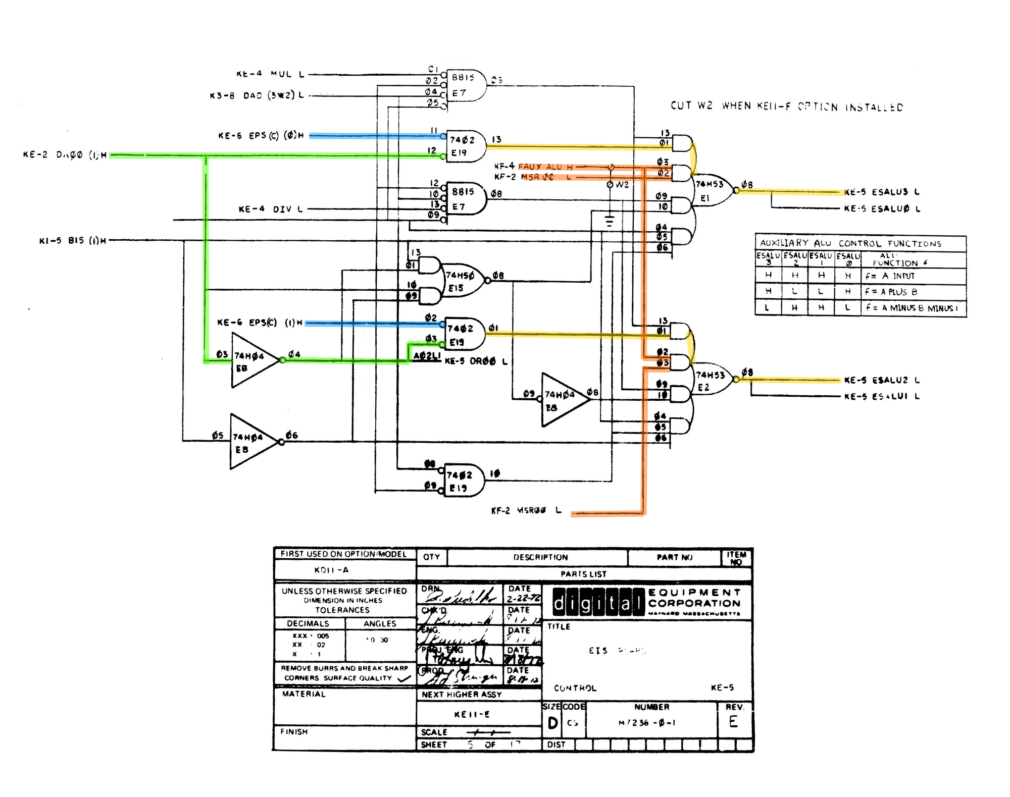
After poking around the circuit for a while I notice that FAUX ALU was high. From the name I concluded that it was Floating Point Auxiliary ALU Control, this signal comes from the FIS board and might explain why swapping boards breaks Unix and presumably some functions of the EIS.

Tracing FAUX ALU back to the FIS board revealed the culprit. On the oscilloscope, it was immediately clear that the signal on pin 9 wasn’t being respected. The 8815 had effectively become a three-input gate.
The Fix
As before, I replaced the 8815 with a 7425. This fixed the FIS allowing the EIS to operate correctly without interference from the malfunctioning FIS board.
Summary
The EIS was being derailed by the FIS board erroneously asserting FAUX ALU. This caused the EIS multiply and divide operations to malfunction.
The EIS Arithmetic Shift operation was not affected, subsequently the FIS was able to pass its tests because it seemingly does not utilise the multiply and divide operations only Arithmetic Shift.
Discussion
Should FIS board be removed when testing?
I don’t think it’s worth disabling the FIS board — the interface between FIS and EIS is small, and they generally shouldn’t interfere with each other. If they do interfere, that’s a problem you want to identify early.
Is the 7425 an ideal replacement for the 8815?
Technically, is a little slower but has better drive capabilities, have a look at the attached documents.
What could be done to improve the tests?
If DEC was still around, I would make the recommendation that they add some more test to very basic EIS functionality. Likely it does test arithmetic shift but not the multiply or divide.
Needless to say, when testing the FIS board the EIS test should also be run and vice versa to identify any potential situations like this. I only noticed when attempting to boot Unix.