PDP-8/e DCA Instruction Repair

Following the repair of the timing card, it's time to give running the diagnostics a try. So I toggled in the RIM Loader and started it, and the system immediately malfunctioned.
Symptoms
After doing some basic testing I identified that "Memory Reference Instructions" were failing. For simplicity, I decided to focus on the DCA Instruction (Deposit, Clear Accumulator).
When the DCA instruction was run, it loaded the CPMA with the destination address, deposited the data, clear the accumulator and restored the CPMA. However, that final step wasn't working; instead of loading the CPMA with the next address, it was loading 0000, and the system would start to run from 0000.
Initial Theory
0000 is a very specific number, and identical to the value of the accumulator post-clearing. So perhaps the CPMA is being latched with 0 at the same time as the AC is getting cleared. The ALU has previously been validated, so there is no suspect fault in the ALU itself; the same applies to the data paths.
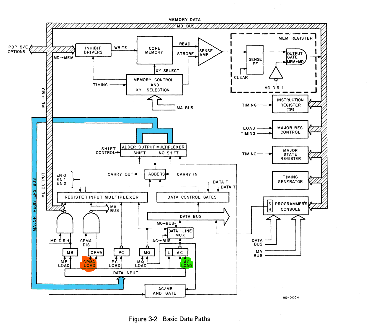
Checking Register Load Signals
With my theory that CPMA was being loaded at the wrong time, I set up the logic analyser to record the suspected signals. I recorded a capture from both a functional and non-functional board. The image below shows the capture:
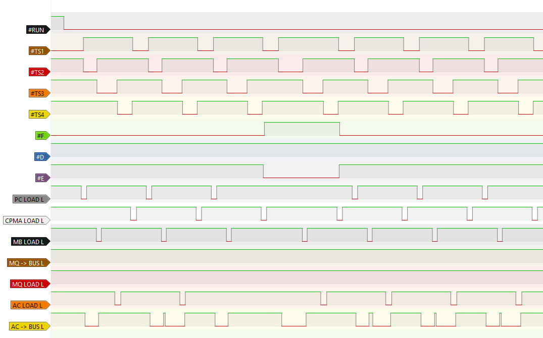
With both captures in hand, I began to compare them against each other. To my astonishment, both captures were identical. This was both good and bad; it means that the fault is relatively isolated, but I had no new information to go on.
Further Investigation
Having disproven my original theory, I didn't have much to go on. I know that the ALU, data paths and register latches are working. The only other major elements left were the ALU control signals and data path mux control signals.
So I set up the logic analyser again with the 8 major ALU and mux control signals. Again, I took two captures, one with the working board, one with the broken board.
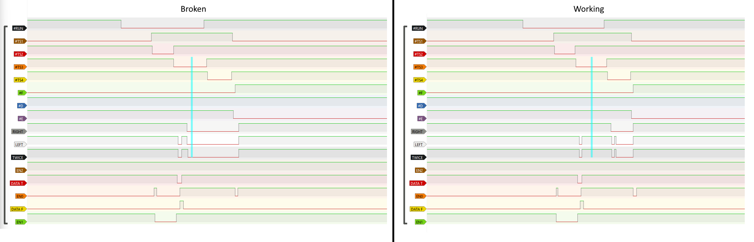
Looking at the captures, it was apparent that there was a problem with three of the ALU control lines. On the working board, they were high in the TS3 state, but on the broken board, the same signals were all low.
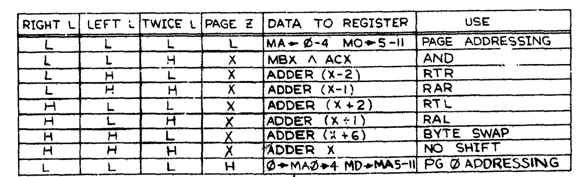
Checking against the ALU truth table shows quite a drastic function difference; the correct mode should just pass the unmodified input directly to the output. Instead, the output was configured for "PAGE ADDRESSING".
The Repair
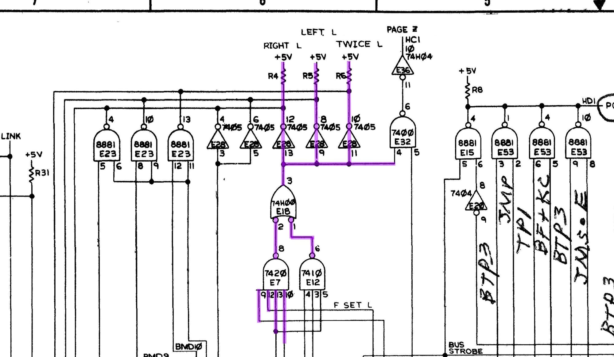
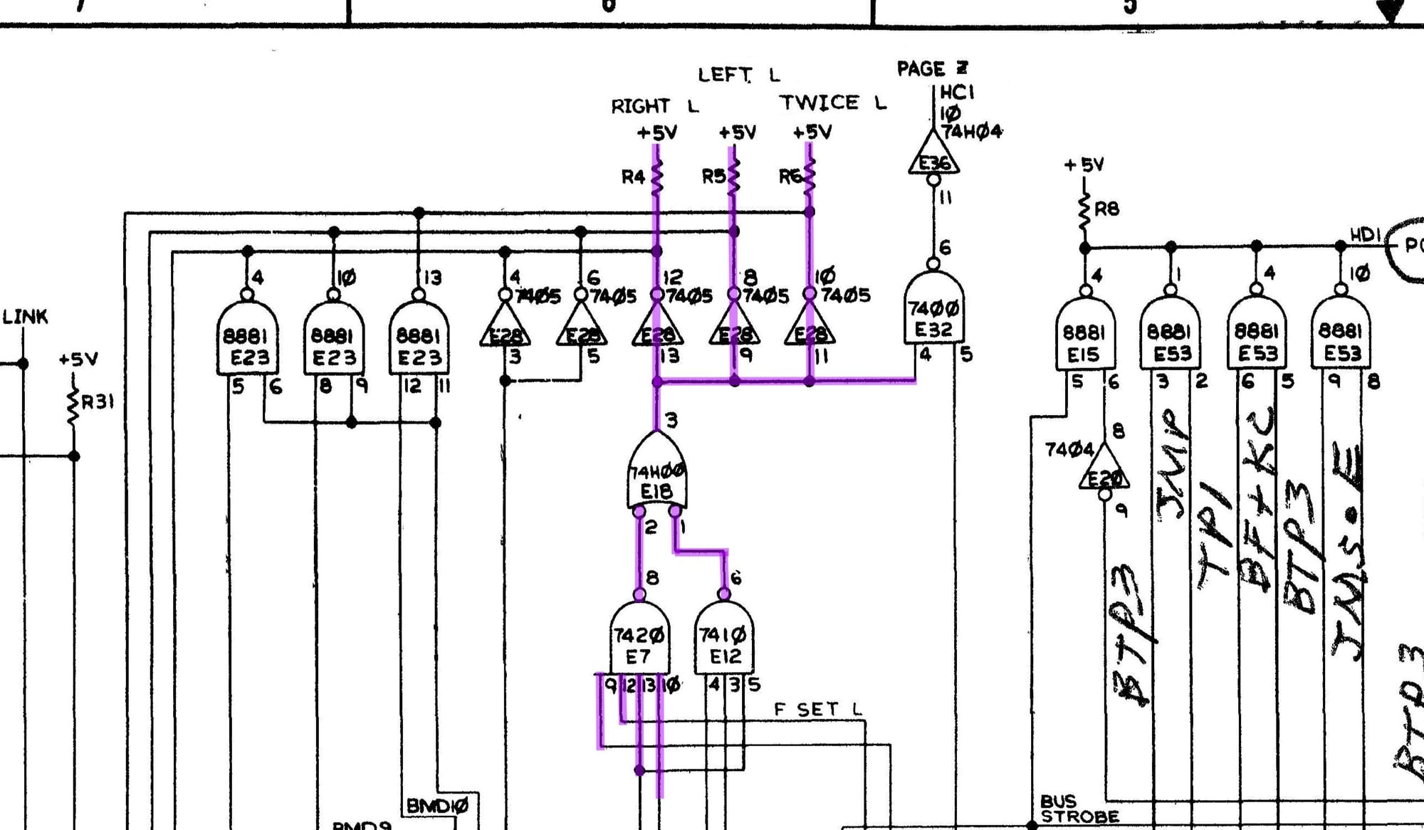
Having identified the primary symptom, it was only a simple matter of tracking down the malfunctioning chip. Working my way back, I found a circuit common to all three ALU control signals.
After a little bit of investigation, I found that E7 was not functioning correctly. Half an hour later, I had swapped the chip, and the system was running correctly and passing all of the tests.