PDP-8e Testing and Initial Checkout

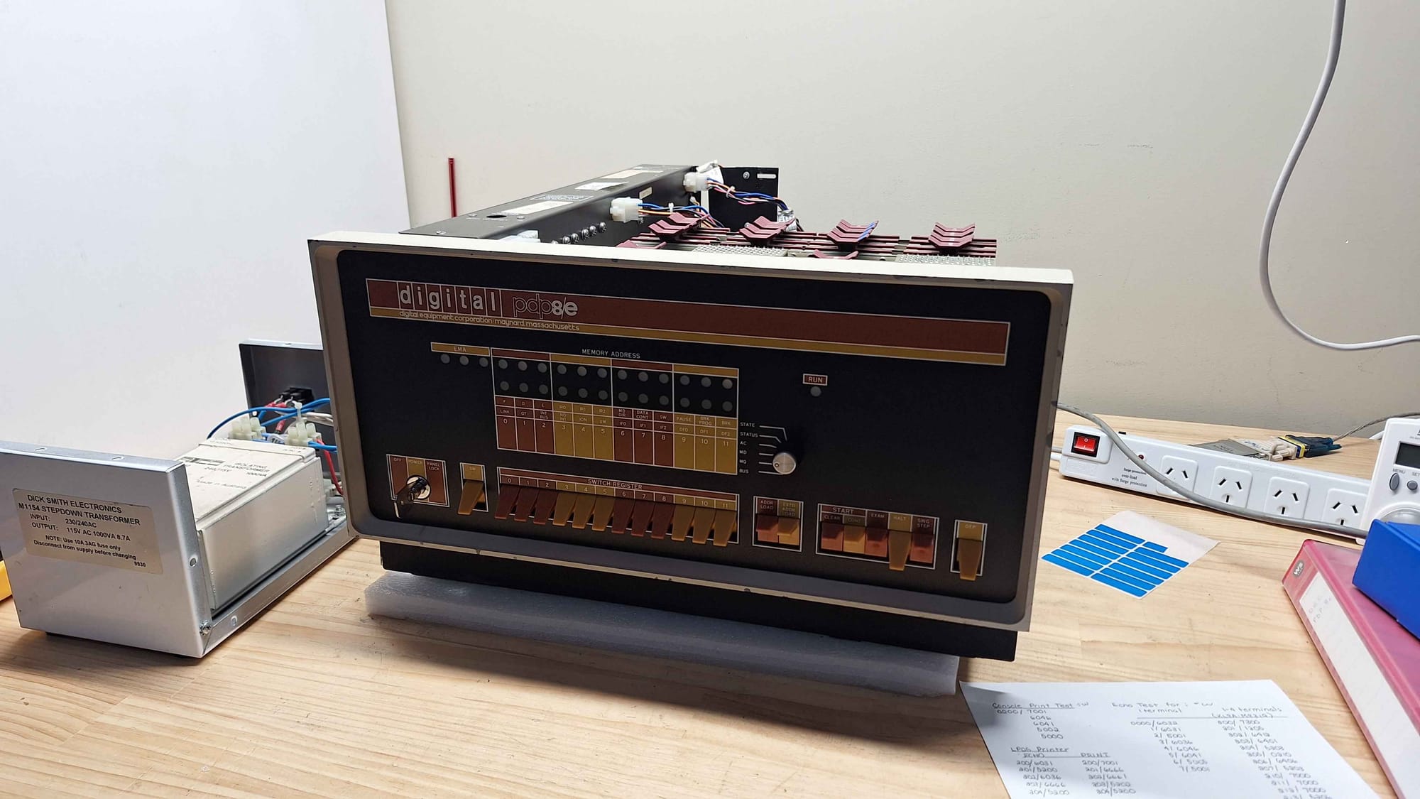
I have been graciously given the opportunity to fix a PDP-8e as my next project. This system is currently configured in a minimal configuration, including only the CPU, UART, memory, and Memory Extension. Additionally, the system came with some spare CPU cards.
Initial Hardware Configuration
| Slot | Module |
|---|---|
| 13 | M837 – Memory Extension |
| 12 | M8655 – UART |
| 11 | Empty |
| 10 | M8320 – Bus Load |
| 9 | Empty |
| 8 | M849 – Shield |
| 7 | Empty |
| 6 | Memory |
| 5 | Empty |
| 4 | M8300 – Major Registers |
| 3 | M8310 – Major Control |
| 2 | M8330 – Timing Generator |
| 1 | Front Panel |
Initial Testing
It's already known that this system has stability problems and that some instructions don't work. But for the most part, the system runs and can run some basic programs without issue (probably).
The following is my observations running various tests as I get a feel for the system and get to know it.
Increment AC (Short)
1        0200          *0200
2
3 00200  7001  START,  IAC             / Increment AC
4 00201  2300          ISZ COUNT       / Increment and skip if 0
5 00202  5201          JMP .-1         / Jump back to increment
6 00203  5200          JMP START       / Jump to START
7
8        0300  COUNT=  0300
9                      $
This program seems perfectly stable; the system was left running for 7 minutes without any crashes or the system locking up. The system draws approximately 1.4A at 240V.
Increment AC (Long)
1        0200          *0200
2
3 00200  7300  START,  CLA CLL     / AC = 0, L = 0
4 00201  7001  LOOP,   IAC         / Increment AC
5 00202  2207          ISZ COUNT   / Increment COUNT, skip if zero
6 00203  5202          JMP .-1
7 00204  2210          ISZ COUNT2  / Increment COUNT2, skip if zero
8 00205  5204          JMP .-1
9 00206  5201          JMP LOOP
10
11 00207  0000  COUNT,  0000
12 00210  0000  COUNT2, 0000
Having spent the time to decompile this program, I was really disappointed to find out it's identical to the previous, except it counts twice. It doesn't even run noticeably slower. The behaviour of this little programme is identical to the short version.
Console Print Test
This test will sequentially print out all possible ASCII characters in a loop. The output looks like this:
?? ¡¢£¤¥¦§¨©ª«¬®¯°±²³´µ¶·¸¹º»¼½¾¿ÀÁÂÃÄÅÆÇÈÉÊËÌÍÎÏÐÑÒÓÔÕÖ×ØÙÚÛÜÝÞßàáâãäåæçèéêëìíîïðñòóôõö÷øùúûüýþÿ
123456789:;<=>?@ABCDEFGHIJKLMNOPQRSTUVWXYZ[\]^_`abcdefghijklmnopqrstuvwxyz{|}~
?? ¡¢£¤¥¦§¨©ª«¬®¯°±²³´µ¶·¸¹º»¼½¾¿ÀÁÂÃÄÅÆÇÈÉÊËÌÍÎÏÐÑÒÓÔÕÖ×ØÙÚÛÜÝÞßàáâãäåæçèéêëìíîïðñòóôõö÷øùúûüýþÿ
123456789:;<=>?@ABCDEFGHIJKLMNOPQRSTUVWXYZ[\]^_`abcdefghijklmnopqrstuvwxyz{|}~
1        0000          *0000
2
3 00000  7001  START,  IAC         / Increment AC
4 00001  6046          TLS         / Print character in AC, clear printer flag
5 00002  6041  WAIT,   TSF         / Skip when printer is ready
6 00003  5002          JMP WAIT    / Wait for printer
7 00004  5000          JMP START   / Repeat forever
8
9                      $
Session 1: This program crashes anywhere between 30 seconds and 2 minutes. The crashes I have seen stopped at addresses 0002 and 0003. When crashed, the address and data lights remain static, but the run light remains on.
Session 2: On another day, I tried exactly the same program, it was about 17° in the room, and the Machine was starting from cold. It ran for about 5 minutes without any issues.
Console Echo Test
 1        0000          *0000
 2
 3 00000  6032  LOOP,   KCC         / Clear keyboard flag and AC
 4 00001  6031  WAITK,  KSF         / Skip if keyboard flag is set
 5 00002  5001          JMP WAITK   / Wait for key
 6 00003  6036          KRB         / Read key into AC, clear keyboard flag
 7
 8 00004  6046          TLS         / Send AC to teleprinter
 9 00005  6041  WAITT,  TSF         / Skip if printer ready
10 00006  5005          JMP WAITT   / Wait for printer
11 00007  5001          JMP WAITK   / Wait for next key
This program ran without any difficulties. Albeit, I did have trouble trying to program it into the machine.
System Startup
Observation 1: Here, you can see that the system has gotten stuck in a state where it's not completing an address load. Soon after, I was able to unstick it by playing with the HALT, CLEAR and CONT. My suspicion is that there is a flip-flop somewhere that gates the major machine cycles, and that on power-up, it was not cleared. Is this indicative of a fault, or is the PDP-8e power-on circuit not always effective?
Startup Issue
Attempts to Improve Stability
From previous experience, the major things that affect system stability are voltage, contacts, and signal integrity. In the following sections, I will explain how I have addressed each of these.
Card Cleaning Contacts
To start with, I removed the cards one by one and thoroughly cleaned the card edge connectors. I clean them using cotton buds and CRC Precision Co Contact cleaner; it's my preference because it does not leave an oily residue behind. I also squirted a liberal amount into the back plane and re-seated the cards a couple of times.
I also took the time to spot clean the board to remove any contamination that was sitting across multiple traces. While I had the boards out, I also spent some time cleaning flux off some of the chips.
While working on the UART card, I found a loose jumper bridge. It had previously been cut; one side was connected, but the other side was loose and spinning around. Given enough vibration or bad luck, it may have made accidental contact so it was removed.
Reordering Cards
With the cards out, it was an appropriate time to re-evaluate the order in which the cards should be installed in a machine. When I first examined the card order, I was a little surprised by the placement of the bus load card. Generally, those kinds of bus termination cards are installed at the end of the bus to reduce reflections and improve bus signal integrity.
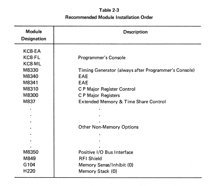
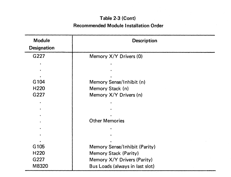
As per the documentation, the Bus Loads should be installed in the "last slot". I take that to mean in the last slot in the backplain. I took the time to reinstall the cards more in line with DEC's recommendation.
Backplane Contact Damage
While I had the boards out, I spent some time inspecting the backplane. I did find a location where some of the plastic had broken off, and two pins were extremely close to touching.
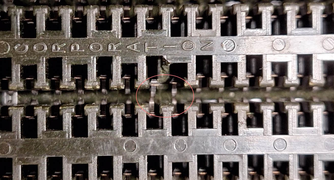
This was slot 11, one that was previously unused. Fortunately, the solution was rather straightforward; all I did was install the UART card into that slot.
Power Connector Cleaning
During some testing, I found that I was losing 0.23 volts between the power supply and logic chips. This was enough to fall just below the 4.75V minimum voltage for TTL chips.
To address the voltage drop, I cleaned and tightened all of the connectors. Both the MATE-N-LOK and the quick-connect spade terminals.
After cleaning the contacts, the voltage I was able to read on the chips was up to 4.9V. Not perfect, but it's now within speck.
Did we solve the stability problems?
No, it still crashes every couple of minutes. Lots more work to go.
The next step is to try and isolate this fault or try and find other problems. I have been informed that the rim loader does not work properly, so that is probably the next thing to work on.
There is hopefully enough functionality running that I will be able to rewrite the rim loader to avoid any particularly unstable instructions. Doing so well greatly increases the speed at which I can diagnose faults.